- tRFC, tFAW, tRRD, tRRDL and tSTAG control internal DRAM processes and primarily affect stability.
- Many subtimings are interrelated; forcing them too much can reduce performance or cause errors.
- XMP profiles typically offer a very solid balance between security and speed for real-world use.
- Adjusting subtimings only provides marginal improvements compared to optimizing frequency, main timings, and voltage.
When you start tinkering with RAM, the first things you look at are the main timings: CL, tRCD, tRP, and tRAS . But as soon as you delve a little deeper, acronyms like tRFC, tFAW, tRRD, tRRDL, and tSTAG appear , which sound like gibberish and are almost never explained well. Many users notice these values change when updating modules or activating an XMP profile and wonder if they really matter in everyday use, especially for gaming or productivity tasks.
The reality is that these timings are internal parameters that govern how the memory physically works . They don't always translate into more FPS or higher benchmark scores, but they do make the difference between a stable system and one that crashes at the slightest lapse in attention. Furthermore, incorrectly tuning them can have the opposite effect: reduced performance despite having "more aggressive" values. Let's see why this happens and what each timing setting looks like.
What are tRFC, tFAW, tRRD, tRRDL, and tSTAG in RAM?
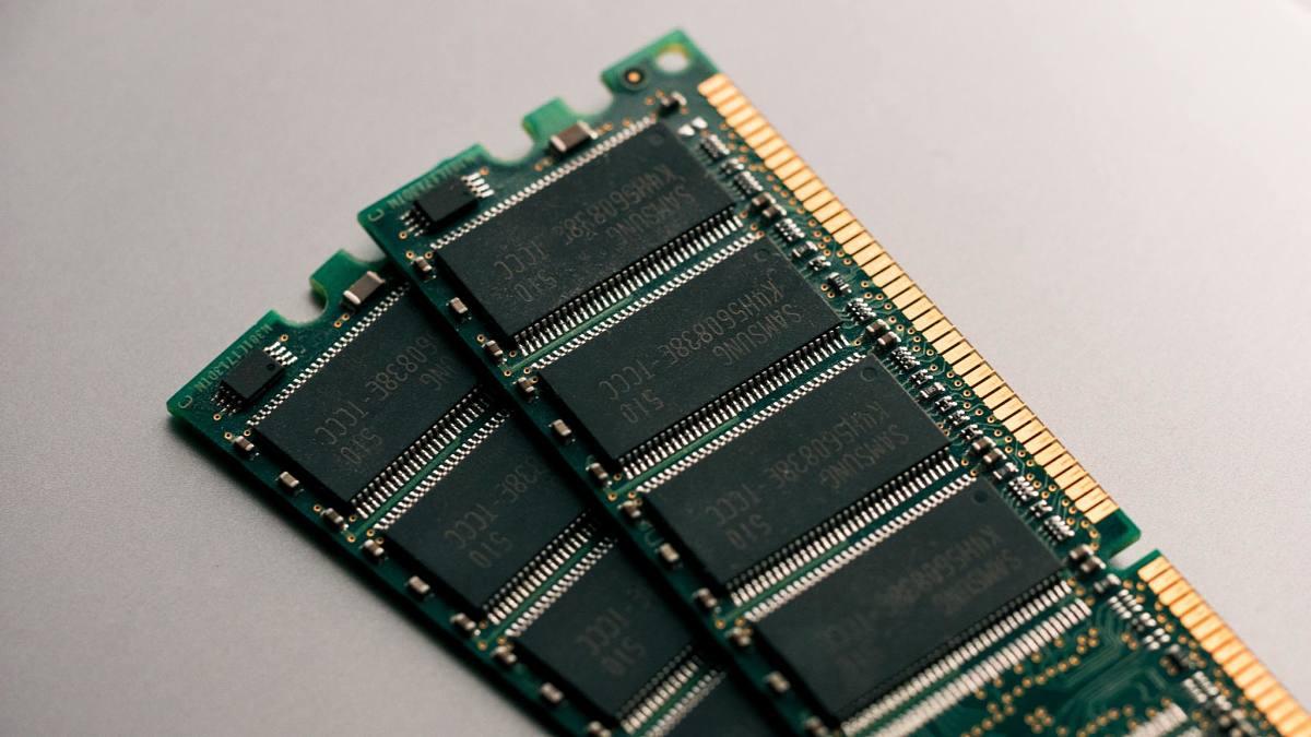
In the RAM specifications, you'll see that, in addition to the four main timings, there's a long list of sub-timings. Among these are tRFC, tFAW, tRRD, tRRDL, and tSTAG, which control critical internal operations of the DRAM chips . They don't directly manage latency between the CPU and memory, but rather refresh times, activation times between banks, and certain safety limitations to prevent the chips from becoming overloaded.
Many module manufacturers, such as G.SKILL, Crucial, or Patriot, program these subtimings into the XMP or DOCP profiles after extensive stability and performance testing . That's why sometimes, when you try to manually "improve" them (by drastically lowering values), the result is a strange mix of instability, errors in MemTest, or even performance losses in synthetic benchmarks like AIDA64 or Membench.
It's important to understand that, as long as the main timings are correct, these sub-timings fine-tune how the workload is distributed between memory banks and rows . Adjusting them might make a difference of thousandths of a second or small percentages in benchmarks, but the absolute priority is ensuring system stability under all loads: gaming, editing, prolonged testing , etc.
The role of tRFC: memory row refresh
The tRFC (Row Refresh Cycle Time) timing is one of the most important of the secondary timings. It controls the minimum time the RAM must wait to complete a row refresh operation . Because DRAM chips lose charge over time, they need to refresh their contents periodically to avoid data loss; tRFC determines how long a row is "locked" during this refresh.
In some BIOSes, you'll see several related fields: tRFC (in cycles), tRFC (ns), tRFC2, and tRFC4 . The value in nanoseconds is the real-time, and the others are expressed in internal clock cycles. In a practical example with an ASUS ROG Strix G15 Advantage Edition, the stock RAM and a Crucial DDR4 3200 MHz CL22 RAM module had exactly the same refresh rate values.
- tRFC (ns) – 350
- tRFC – 560
- tRFC2 – 416
- tRFC4 – 256
Although the new RAM was double-sided and had improved subtiming in other areas, the refresh rate was fixed at the same safe values . This is quite common: the manufacturer prioritizes long-term stability, especially in laptops or computers that will be powered on for many hours.
There is even a rule widely used in the overclocking community to relate these times: tRFC2 ≈ tRFC × 0,768 and tRFC4 ≈ tRFC × 0,46 . These are indicative ratios that help maintain consistency between the different refresh parameters when manually adjusting the base value.
To calculate an approximate tRFC in cycles from an estimated value in nanoseconds, many enthusiasts use a simple formula: tRFC (cycles) ≈ (tRFC_ns × memory frequency) / number of channels . For example, for 180 ns at 3600 MHz in dual channel : 0,18 × 3600 / 2 = 324 cycles. This type of calculation is useful for getting a general idea, but it's essential to validate it with stability tests.
tFAW: activation limiter in time window
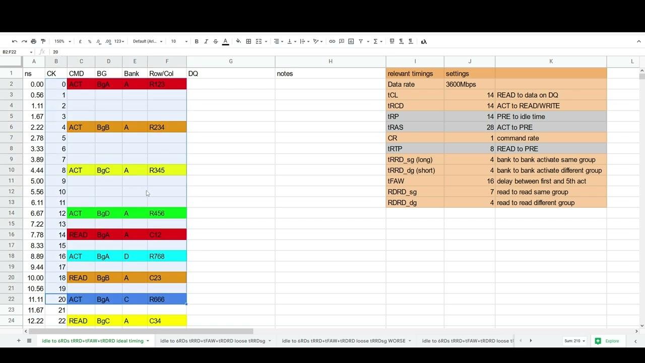
The tFAW (Four Activate Window) parameter is one of the most confusing. It defines a time window in which only a maximum number of row activations can be performed within the same rank, usually four. It's a kind of "traffic light" that prevents the chip from overloading by opening too many rows at once.
A well-known rule in overclocking communities (and one that many users attribute to Korean guides on forums like OCN) states that tFAW should generally be four times tRRDS . That is, if tRRDS is 4, a tFAW of around 16 would be a very tight margin. In practice, commercial memory modules usually have a much higher tFAW (40, 44, 48…) to ensure a safety margin.
It has been observed in several tests that, when tFAW is lowered below a certain point, performance begins to worsen instead of improve . One user who was fine-tuning their kit with XMP II found that:
- By reducing tFAW from 44 to 40, writing performance improved slightly (within the margin of error).
- As tFAW was further reduced below 40, read/write speeds and latency degraded.
Another case, with a Patriot Viper Steel kit running at high frequency, showed an even clearer effect: increasing tFAW and tWR from 12 to 24 "for safety" caused a significant drop in performance in Membench , even though memory tests showed no errors. When the user returned to more aggressive values and properly adjusted other subtimings like tRFC, they obtained much better benchmarks without losing stability.
Practical conclusion: tFAW is not simply a matter of "the lower the better ." It must be related to tRRDS and the internal design of the kit. Values that are too high or too low will ultimately limit performance, even if the memory passes basic error tests.
tRRD and tRRDL: minimum time between row activations
The timings tRRD (Row to Row Delay) and tRRDL (Row to Row Delay Long) define the minimum interval between row activations in different banks. tRRDS typically refers to the short delay, and tRRDL to the long delay , which comes into play when the activation affects banks further apart within the chip.
In practice, these parameters limit how quickly the memory controller can jump between different rows to service requests. If you set them too low, you may encounter instability or other security mechanisms (such as tFAW) that will slow down the process.
In the example of the ASUS ROG Strix G15, when switching from the stock RAM to a dual-rank Crucial DDR4 3200 MHz CL22 kit, this difference occurred:
- Serial: tRRDS 9, tRRDL 11, tFAW 48, tSTAG 12.
- New RAM: tRRDS 4, tRRDL 8, tFAW 34, tSTAG 9.
Although the main timings remained the same, the subtiming was noticeably more aggressive on the Crucial RAM. Even so, in real-world use (gaming and productivity), the performance differences were minimal . The change was more noticeable in synthetic benchmarks than in everyday use.
Another user adjusting their XMP II profile encountered a curious situation with tRRDL: when lowering tRRDL from its initial value, read, write, and latency results fluctuated within the margin of error . With tRRDL set to 8 or 9, the results were virtually equivalent to the base configuration; reducing it further caused performance to degrade. In other words, there's an optimal point beyond which further adjustments no longer help.
Many advanced guides recommend that tRRDL not be pushed too far below the values suggested by the XMP profile , especially with dual-range (DR) modules, where the electrical requirements are higher. The system's own behavior ends up "paying the price" for these excesses, sometimes with a performance decrease that seems illogical on paper.
What is tSTAG and why is it hardly ever talked about?
tSTAG is one of those subtiming settings that often appear in advanced BIOS versions and that almost no one touches. It usually refers to a kind of "staggering" or staggered delay between certain internal commands , designed to avoid signal conflicts when certain operations are chained together.
In the practical example of the ASUS laptop's RAM, switching from the stock memory to Crucial changed tSTAG from 12 to 9. This is a slightly more aggressive adjustment, but in practice, it didn't produce a measurable jump in everyday benchmarks . This type of subtiming is adjusted more by the internal requirements of the chip and controller than by a direct impact on performance.
That's why many experts on forums agree that the priority when overclocking is to focus on the main timings and key sub-timings such as tRFC, tFAW, tRRD, tWTR, and tWR . Parameters like tSTAG are usually left to the BIOS auto settings or the values defined by the manufacturer.
While you can experiment with them if you're looking to squeeze out the last 1% of performance, they're not the first place to look if you want a clear improvement for gaming or to speed up productivity tasks . The risk of causing strange instabilities without any appreciable gain usually outweighs the potential benefit.
Relationships and basic rules between timings
Anyone who has browsed overclocking forums will have seen countless rules and formulas for relating timings. Some of the most frequently used are based on accumulated community experience , such as those a user gathered from a well-known Korean "engineer" at OCN. These rules aren't set in stone, but they serve as a starting point.
There are also several common ways to calculate TRAS :
- tRP + TRAS ≈ tRC
There are also several common ways to calculate TRAS:
- TRAS ≈ tRCD + tCL (the most used).
- TRAS ≈ tCL + tRP.
- tRAS ≈ tRCD + tWR + tBL (tBL is the Burst Length).
Regarding tWR (Write Recovery Time) , there are a series of "rules" to prevent it from becoming excessively low:
- tWR ≥ tRRDS + tWTRS
- tWR ≥ tCL + tRTP
- tWR ≥ TRAS − tRCD
If these minimum requirements aren't met, the system might pass some light tests but fail under heavier loads or after several hours of use . It's the typical "it seems stable, but the game crashes after a while" scenario.
Another interesting group of relationships affects tRDWR (Read to Write Delay) . In some configurations, the following reference is used:
- tRDWR ≈ tRCD_RD / 2 as a base value.
From there, certain "safe" values are considered depending on whether the RAM is single-rank (SR) or dual-rank (DR) :
- 2× SR: tRDWR = tRCD_RD / 2
- 4× SR: tRDWR = tRCD_RD / 2 + 1
- 2× DR: tRDWR = tRCD_RD + 2
- 4× DR: tRDWR = tRCD_RD + 4 (some people say that the value +3 may allow the use of a lower tWRRD).
These are all guidelines to avoid absurd combinations. You can deviate slightly from these rules to fine-tune things, but the further you stray, the more likely you are to encounter subtle errors that only appear after many hours of stress or in certain applications.
tWR, tWTR, tRTP and tCWL: subtimings that can be noticed
In addition to tRFC, tFAW, and tRRD, there are other highly relevant sub-timings in RAM behavior: tWR, tWTRS, tWTRL, tRTP, and tCWL . Several users have shared specific experiences where adjusting these values has clearly improved both stability and performance.
tWR (Write Recovery Time) marks the time the memory must wait after a write operation before it can perform certain subsequent operations. In the case of a user who followed the DRAM Calculator to relax tFAW and tWR from 12 to 24, the effect was striking: the memory became stable in tests like MemTest86, but the times in membench worsened dramatically . In other words, stability had been gained, but at the cost of severely impacting performance.
When that same user returned to more aggressive timings and simultaneously fine-tuned other parameters such as tRFC, tRFC2, and tRFC4, he achieved a configuration with CL15, tRCDRD 16, and very tight subtimings, stable in multiple runs of memtest and Karhu . He even slightly increased VDDP and VDDG to 0,9 V and 0,95 V to meet the recommended minimums, while maintaining the RAM voltage around 1,38 V and the SoC at 1,1 V.
Regarding tWTR (Write to Read), it's usually divided into tWTRS (Short) and tWTRL (Long). A common recommendation is to set tWTRL to double or triple the tRRDS , ensuring sufficient buffering between writes and reads to avoid overloading the banks. Again, this is more of a practical guideline than a rigid rule, but it helps prevent problematic combinations.
tRTP (Read to Precharge) and tCWL (CAS Write Latency) also play a role. There's a fairly common guideline: tCWL is usually set equal to tCL . If they don't match, the difference is often adjusted to a logical step, increasing or decreasing the value to maintain consistency. Lowering tCWL too much can cause instability without a measurable improvement outside of very specific benchmarks.


Passionate writer about the world of bytes and technology in general. I love sharing my knowledge through writing, and that's what I'll do on this blog, show you all the most interesting things about gadgets, software, hardware, tech trends, and more. My goal is to help you navigate the digital world in a simple and entertaining way.