
Solid Edge and SolidWorks: Would you like to know which is better? A closer look at Solid Edge and SolidWorks can help readers determine which product will best suit their needs. Rolling Stones or the Beatles? Marmite or Vegemite? Solid Edge or SOLIDWORKS?
These are the questions that have plagued humanity for generations. In this article, we will address at least one of these dichotomies and hopefully allow you to make an informed decision about which CAD package is best for you.
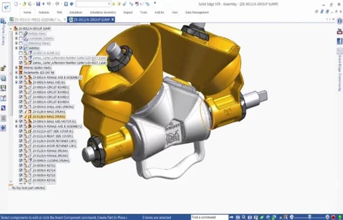
Comparison – Solid Edge and Solidworks
First of all, we need to declare any conflict of interest. Most SOLIDWORKS users and write articles primarily related to that particular CAD package. Some have used Solid Edge on a few occasions, mostly for basic modeling. Therefore, we will write this article primarily as Solid Edge newbies and from the perspective of a SOLIDWORKS user.
Here you can read about: How to Move an Object in SketchUp (Or Parts of It)
For those of you who are no longer students, there is a 45-day trial available for the full version of Solid Edge on the Siemens PLM Software website, which you can find at this link.
Another nice feature of Solid Edge is the monthly subscription service. This is particularly good if you have a small staff and your CAD usage varies from month to month, where it may not be optimal to pay for a full annual license when positions become empty (when engineers can be assigned to other tasks for example).
You can find more details about the monthly subscription here . Additionally, if you have a small startup with less than $1 million in funding and less than $10 million in annual revenue, you may be eligible for a free 1-year subscription.
For the purpose of this review, we'll be using the 45-day trial version, which promises part modeling, assembly design, drawing, and simulation, as well as providing access to videos and online training, and also to the Solid Edge online community.
Solid Edge and Solidworks Compatibility
Like SOLIDWORKS, later versions of Solid Edge are incompatible with 32-bit machines. According to Siemens, Solid Edge ST9 is 64-bit only. Solid Edge ST6 was the last 32-bit version of Solid Edge.
The good news is that Siemens still offers a student version of ST6 on its website. The bad news is that if you're used to 32-bit CAD software and want to use a version of Solid Edge from 2015 or later, you'll need a new computer.
Solid Edge and Solidworks – Usability
When you start Solid Edge ST9, you have the option to open a document or create a new one based on several templates. Templates include ISO Metric Part, ISO Metric Assembly, ISO Metric Draft, and so on.
The default values in this list can be changed to ANSI inch or metric, GB metric, or whatever standard you prefer, so you can use the standards you prefer the next time you open the software. It is quite similar to SOLIDWORKS in that it offers options for parts, assemblies, or drawings as default options when you open a new file.
- For this exercise, you open a new part document, select ISO Metric, and the blank design window opens on the screen.
It doesn't take long to re-familiarize myself with the software layout.
On the right is a hidden panel for community and online features, on the left is a panel for what appears to be the SOLIDWORKS design tree, and hidden to the left of that panel are some panels for simulation, sensors, layers, and whatever else you like.
The top panel is similar to SOLIDWORKS and contains sketches, surfaces, and other features used to create designs.
Solid Edge and Solidworks – Modeling
Let's see if our SOLIDWORKS knowledge will allow us to do basic modeling, without the need to consult the manual or tutorials. We want to see how intuitive the software is.
- Step 1:: We draw a circle without a particular dimension and click on the button Home>Select from the top panel (see Figure 1).
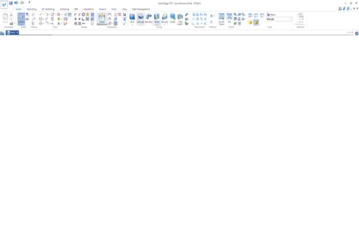
NOTE : It appears that everything is controlled from this selection arrow. According to the tooltip that appears when I hover over the arrow, the selection arrow will allow me to select an item for modification.
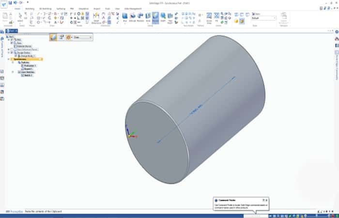
In fact, when we click on the circle, an extrusion handle appears. I drag it outwards and a cylinder is formed. So far, it's pretty easy.
- Step 2:: We continue playing with the solid functions in the top panel. Adding fillets to the edges is easy.
- Step 3:: We added a thin feature, turning the cylinder into a cup (see Figure 2).
This is all very easy, and we haven't had to touch the keyboard yet. For the most part, it seems to work largely with the mouse, and functions can be accessed from the main panel at the top. We haven't had to scroll down through any long menus yet.
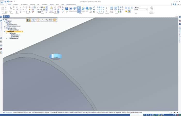
The hole feature seems pretty easy to use.
- Step 1:: Clicking this option allows you to drag and drop a hole with specific geometry and features (such as a countersink) onto the main part.
- Step 2:: The graphics window shows how the hole will appear on the part in real time (see Figure 3).
In conclusion, in terms of basic solid modeling, we don't think there's much difference between the two products. It depends on what you're used to. If you've been using SOLIDWORKS for a decade, you won't find modeling in Solid Edge too complicated. And conversely, if you're a new Solid Edge user, it won't take you long to get up and running.
Solid Edge and Solidworks – Simulation
So, we've had a brief look at solid modeling. Now, let's look at another feature I use quite a bit in SOLIDWORKS: simulation.
SOLIDWORKS works pretty well for simulation. It's intuitive, produces nice wireframes/animations, and the computational engine is pretty accurate.
How does ST9 compare? Well, in terms of the engine, ST9 is using the NX Nastran solver, which is one of the best finite element analysis (FEA) solvers out there, given that Nastran has been around for decades and has had time to improve.
We just want to run a simple simulation to see how intuitive the process is.
- Step 1:: We take the cylinder and then click on the simulation tab on the top ribbon.
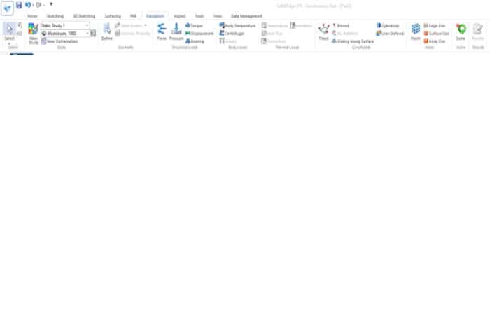
- Step 2:: The simulation ribbon is quite intuitive and, reading the icons from left to right, gives a good indication of the sequential workflow (see Figure 4).
- Step 3:: From left to right, we first click on new study, then we select a static study and below that we select the material.
NOTE : The software GUI guides the user from the beginning (left) to the final goal, which is clearly the resolution icon.
After setting up my material, forces, constraints, etc., I'm ready to run the simulation.
- Step 4:: We click on the mesh button and we have the option to mesh only or mesh and solve.
- Step 5:: We choose a mesh size and then select mesh and solve.
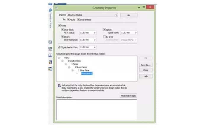
NOTE : If any errors are present, a geometry inspection window will open, allowing you to navigate through a geometry tree to pinpoint the source of the error. You can then resize the mesh or even revert to the model geometry to correct it and remesh. This is much easier to use than SOLIDWORKS. In SOLIDWORKS, if the analysis fails, the information is vague and doesn't offer much assistance.
In ST9
In ST9, fault identification is much more intuitive. Figure 5 shows the geometry inspector.
- Step 1:: We run the simulation and we can see some different display options.
NOTE : We can animate, capture screenshots, change the type of frame (von Mises, scrolling, etc.).
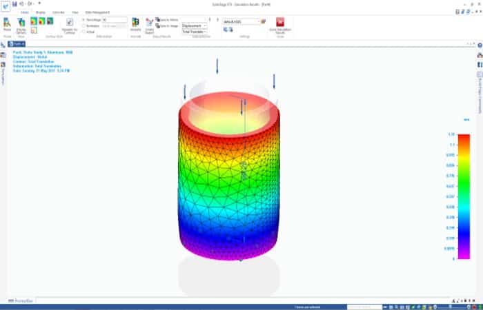
In terms of content, it seems to have the same information as SOLIDWORKS (only the workflow is much clearer). The displacement diagram in Solid Edge is shown in Figure 6.
Solid Edge and Solidworks – Other characteristics
All in all, the differences between Solid Edge and Solidworks are very small. SOLIDWORKS can render just like Solid Edge. Both products have simulation capabilities. SOLIDWORKS seems to have deeper simulation (especially for fluids), and Solid Edge has a better solver and is easier to use. So, at first glance, there isn't much difference between the two. But scratch a little deeper and you'll see that what sets the two apart is what separates them completely.
Synchronous Technology is that one thing.
You see, SOLIDWORKS is history-driven, and everything you create with the software is based on (and tied to) everything that came before it. This means that if you want to go back and add a chamfer to an edge that I made a dozen moves earlier, and that edge is constrained to other features that were created after it, then you could lose everything created after that edge.
This “ feature ” of SOLIDWORKS really means that you have to plan your work in advance and there isn't much room for improvisation.
Synchronous Technology in Solid Edge eliminates all of that and allows geometry to be created and modified on the fly, regardless of the order in which previous elements were created.
Conclusion
As you can see, these are the differences between Solid Edge and Solidworks.
In general terms
Overall, ST9 seems to be fairly easy to use and seems to aim to keep the user away from the keyboard and firmly based on the mouse.
In terms of functions
In terms of functionality, it has practically the same as in SOLIDWORKS, and all the basic surface and solid modeling functions (extrude, cut, transition, sweep) are present in both packages.
The simulation package
ST9's simulation package is easier to use and more intuitive and seems to run a bit faster than SOLIDWORKS. Having seen the renders from both packages, I can say that there isn't much difference between the two. You can use the same rendering engine (KeyShot, for example) with any CAD package, so they are both pretty much the same in that regard.
In terms of learning
For a new user learning CAD software, we believe that ST9 will provide a gentler learning curve to get better models, while SOLIDWORKS will take much longer to get used to (but may have more options in terms of simulation and plastic mold design).
That's ultimately what it comes down to. If we were to advise someone who has no experience with either package on which CAD program to use, I would say it depends on the job you will be using the software for.
You might also be interested in reading about: How to Create a Poster with Photoshop
For ease of use, fast learning curve, increased productivity, and easier modeling, I would recommend Solid Edge. If, like me, you are a long-time SOLIDWORKS user and are thinking of trying Solid Edge, then I would recommend getting a trial version or a student version and seeing for yourself.
In terms of prices
The free edition for students, the free annual subscription for startups, and the monthly subscription lower the financial barrier to accessing the software, which is another good reason to try Solid Edge. We hope this information has helped you.

My name is Javier Chirinos and I am passionate about technology. Ever since I can remember, I have been interested in computers and video games, and that passion has turned into a job.
I have been publishing about technology and gadgets on the Internet for over 15 years, especially in mundobytes.com
I am also an expert in online marketing and communication and have knowledge in WordPress development.