- G-code defines the geometry and movement of CNC machines and 3D printers.
- The M-code controls auxiliary functions such as spindle, coolant, and tool changes.
- CAD/CAM and slicers automatically generate G and M codes, but understanding them is key.
- Mastering these codes prevents errors, improves accuracy, and optimizes production.
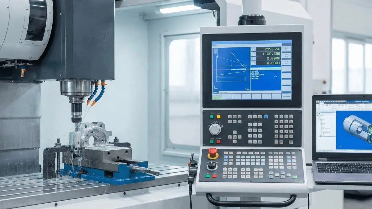
If you work with CNC machines or 3D printers , sooner or later you'll come across the famous G-code and its inseparable companion, M-code. To many, it sounds like Martian language, but in reality, they are simply highly structured instructions that the machine understands perfectly. Understanding what they say and how they combine is key to no longer working "blindly" and to having real control over machining or printing.
Think of your machine, no matter how expensive or modern it is, as being quite "simple": it only knows how to move along X, Y, and Z coordinates, rotate a spindle, or extrude material when you tell it to. Everything else is handled by G-code and M-code. In this article, we'll calmly break down what they are, how they originated, how they differ, how they're used today with CAD/CAM and slicers, what typical errors they cause, and we'll even look at examples of more complex programs, both for CNC lathes and 3D printing.
What is CNC machining and why does it rely so heavily on G-code and M-code?
CNC machining is essentially the use of computer numerically controlled machines (lathes, milling machines, machining centers, etc.) to manufacture parts with a precision that would be impossible to achieve manually and repeatedly. The numerical control defines positions, speeds, and trajectories; the machine obeys.
Among its advantages are extremely high precision, efficiency in material removal , the ability to work with very complex geometries and brutal repeatability: if the program is well done, you can produce 10 or 10.000 virtually identical pieces.
Before computers as we know them today existed, machinists used punched cards or tape to encode instructions. Punching holes in the correct sequence was a slow and fragile process: if a card was damaged or lost, the work was ruined and production ground to a halt.
With the advent of numerical control and the first computers, operators began manually entering lines of code . This was an improvement, but for complex parts with many operations, it became extremely tedious and prone to typing or calculation errors.
Today, the situation is very different: we use CAD software for design and CAM programs to automatically generate toolpaths. The CAM software itself produces the G-code and M-code files ready for the machine to execute. That doesn't mean, however, that understanding what's inside isn't vital for reviewing, optimizing, correcting, and, when necessary, programming by hand.
How CNC programming controls machines
In a typical workflow, the programmer prepares the machining environment in the CAM software: part model, tool model, tool selection , and toolpaths for each operation (roughing, finishing, drilling, tapping, etc.). From all of this, the software generates the CNC program composed of blocks of instructions.
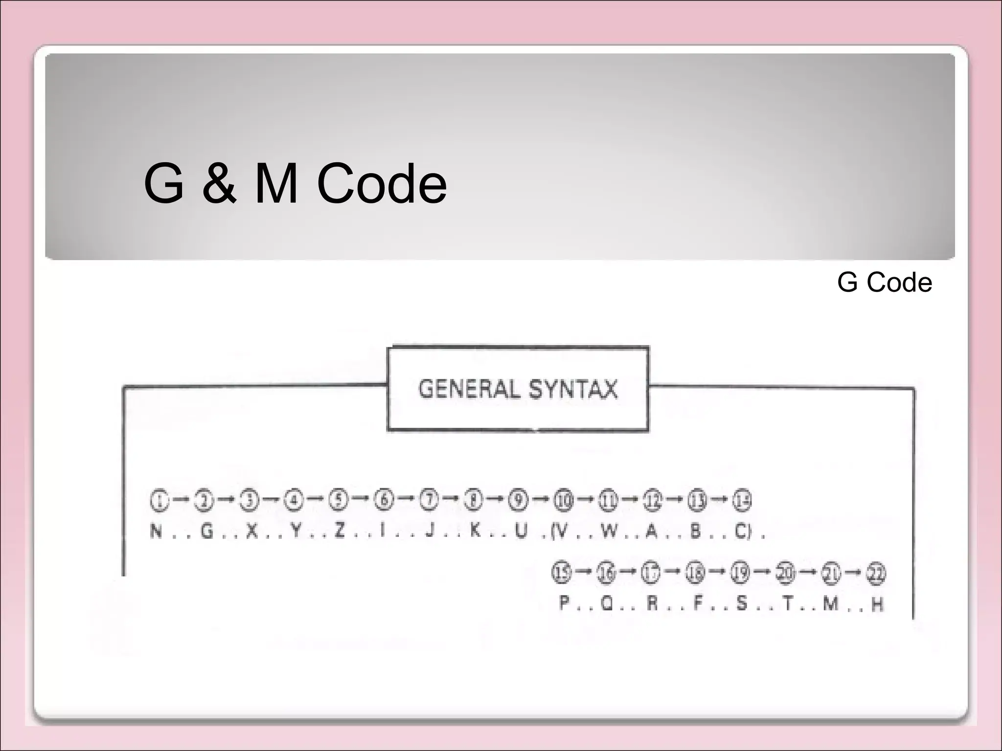
Each block is typically a line of text with a G-code, optionally an M-code , and various parameters: X, Y, Z coordinates, radii, feeds (F), spindle speed (S), tool number (T), etc. The control interprets these blocks sequentially and moves the machine or changes its state according to what is written.
In practice, the program typically combines movement instructions (G-code) and auxiliary functions (M-code) along with some additional commands such as F, S, T, or N for numbering lines. The logic is: the G-code governs "how" the machine moves , while the M-code governs "what" the machine does in terms of hardware functions.
Although CAM saves a lot of work, when the part is sophisticated, post-processing may require manually checking cycles, offsets, feeds, or safety sequences. In complex projects, it is not uncommon for code generation, adjustment, and validation to take days or even weeks.
What is G-code in CNC and 3D printing
G-code, also known as RS-274 or ISO-code, is the standard geometric programming language for CNC machines ( differences between machine code and bytecode ). The "G" stands for "geometry": it describes how the machine should move in space and with what parameters.
In traditional CNC (lathes, milling machines, lasers, etc.), G-code indicates toolpaths, work planes, feed rates , and other information related to the tool's movement relative to the workpiece. In 3D printing, it does exactly the same thing, but applied to the printer's axes and the extruder.
A typical G-code command begins with the letter G followed by a number, for example G00, G01, G02, G03, G17 , etc. Each combination has a very specific meaning. Often, the line includes additional parameters such as X, Y, Z, R, F, S, or E (in 3D printing, for the extruder).
Although there are standards (ISO 6983, DIN 66025, Siemens dialects, FANUC, Haas, among others), each control may add extensions or variations . Furthermore, some formatting details change between manufacturers: for example, one machine may accept G3 and another require G03, or allow the omission of certain zeros and spaces.
In all cases, the basic idea is the same: a sequence of blocks that, executed in order, make up the entire tool path and, therefore, the final shape of the printed piece or object.
Letters and common parameters in G-code
In addition to the letter G, the language uses other letters to indicate important parameters . In classic CNC machining, we find, among others:
- X AND ZCartesian coordinates that position the tool or workpiece in three dimensions. X and Y are usually the horizontal plane, Z the depth or height.
- A: rotation or spin around the X axis (in multi-axis machines).
- R: radius of an arc when performing circular interpolation.
- I, J: incremental components of the center of an arc in circular interpolations.
- N: program line or block number.
- F: feed, that is, cutting or displacement speed in machining operations.
- S: spindle speed, in revolutions per minute.
- T: tool to be used in combination with instructions such as M06.
In FFF/FDM 3D printing, the letter E also appears very often to indicate the amount of extruded filament , along with positioning commands such as G0/G1 on X, Y and Z.
Main G-codes in CNC machining
Some of the most common G-codes in CNC milling machines and lathes are the following:
- G00 – Rapid Positioning: Move the tool as quickly as possible to a specified coordinate, without intending to cut. This is used for approaches and retreats where the only important thing is to arrive quickly and without colliding.
- G01 – Linear Interpolation: It commands movement in a straight line between two points with a specified feed rate F. It is the classic command for straight cuts and contour machining.
- G02 – Circular time interpolation: Draw arcs or circles following a clockwise direction, usually using X, Y (or X, Z / Y, Z depending on the active plane) and a radius R or a center I, J.
- G03 – Counterclockwise circular interpolation: Same as G02 but in reverse, very useful for profiling rounds, circular grooves or curved pockets.
- G04 – Pause or stay: It forces the machine to stop for a specified time. This is used to allow the spindle to stabilize, a tool to cool, or for a coolant to take effect.
- G17, G18, G19 – Plane selection: G17 activates the XY plane, G18 the XZ plane, and G19 the YZ plane, which is essential when working in multi-axis mode or when interpolating arcs outside the standard plane.
- G21 / G20: They define the system of units, usually G21 for millimeters and G20 for inches.
- G43 – Tool Length Compensation: It takes into account that each tool has a different length and applies the appropriate corrector so that the actual machining depth is as desired.
In lathes, specific codes are also common, such as G71 for longitudinal roughing cycles , G70 for profile finishing, or G76 for cyclic threading, which allow you to define a contour and let the control automatically generate the famous "ladder" of intermediate passes.
Advanced example of G-code on a CNC lathe
To see the real potential of these cycles, look at this typical scenario: we start with a cylindrical billet and want to rough out large amounts of material with few lines, leaving some excess material for a finishing pass and finishing with a thread.
In a lathe program we could start by defining the initial material size with a standard instruction in the simulator, identifying the program with a number such as O0001, selecting the metric system with G21 and setting the feed per revolution mode with G99.
Next, a tool change is ordered with something like M06 T0101 (tool 1 with its offset 1), the spindle revolutions are defined in G97 mode (constant RPM) with S1800 M03 to rotate clockwise, and it is quickly positioned with G00 close to the workpiece (for example X26 Z2).
Then, using G01, the billet can be faced through the center (X-1 F.05), returned to the safe position, and entered into the well-known roughing cycle G71. This cycle is defined in two lines, specifying depth of cut U, clearance R, initial block P and final block Q of the contour, allowances U and W, and feed F.
The contour lines between, for example, N1 and N2 are described below: a facing up to X0, a feed in Z, an arc G03 with a specific radius, turning, and coning. The important thing is that the profile is monotonically increasing or decreasing in diameter for the cycle to function correctly.
Once the roughing operation is complete using G71, a G70 P1 Q2 cycle is launched to perform the finishing operation , following the same contour, using the fine speed and feed rate. Afterward, the carriage can be set to reference using G28 U0 W0, the spindle stopped with M05, a threading tool can be switched to T0303, and a G76 cycle can be activated to generate a thread with multiple passes and parameters for depth, angle, pitch (F1.5, for example), and bore.
Finally, the carriage is moved back to the safe position (G28 U0 W0) and the program ends with M30 (end and rewind) or M00 (stop without rewinding). This entire process can be described with very few program lines thanks to fixed cycles , which greatly simplifies daily work.
What is M-code and what role does it play
M-code is known as "miscellaneous" or "machine function" code. While G-code deals with geometry and motion, M-code controls auxiliary actions: starting or stopping the spindle, turning on the coolant, changing tools , stopping or terminating the program, etc.
Formally, these are commands that begin with the letter M followed by a number, such as M00, M03, M05, M06, M08, M30 . Each one acts as a switch that turns something on or off or causes the control to change to another state.
An important detail is that, as a general rule, only one M-code is used in each block . Putting two or more on the same line is usually a bad idea because many functions are mutually exclusive: the spindle cannot be starting and stopping at the same time in the same command without the machine malfunctioning.
Unlike G-code, which is more standardized, M-codes vary considerably between manufacturers . The meaning of M03 or M05 is usually the same across most manufacturers, but other codes (pallet change, gripper, special cycles) can change, and even the format (M3 vs. M03) can lead to errors if quality control is strict.
Most commonly used M codes in CNC
Among the most frequent M-codes you will see in CNC programs are:
- M00 – Program Stop: It pauses execution in a controlled manner until the operator presses to continue. It is used for inspections, manual changes, or one-off interventions.
- M02 / M30 – End of program: They indicate that the program has finished. M30, on many controllers, in addition to stopping, rewinds to the beginning of the program to finish it.
- M03 – Spindle in motion (clockwise): The spindle starts clockwise, usually accompanied by an S value of RPM.
- M04 – Spindle in motion (counterclockwise): Same as M03 but rotating in the opposite direction, useful for certain operations or special configurations.
- M05 – Spindle stop: It slows the rotation, a necessary step before changing tools or finishing a cutting operation.
- M06 – Tool change: Instructs the machine to perform an automatic tool change to the tool indicated in T. Essential in machining centers with a tool magazine.
- M08 – Refrigerant ON: Turn on the cooling system (jet, rain, etc.) to maintain temperature and improve surface finish.
- M09 – Refrigerant OFF: It cuts off the flow of coolant, which is very useful just before tool changes or at the end of the operation.
Although many of these codes are similar from one machine to another, it is mandatory to check the specific control manual because some M codes may have completely different functions depending on the manufacturer.
G-code and M-code in FDM/FFF 3D printing
Something very curious happens in 3D printing: although we're talking about a different technology, the core of the control is based on the same G-code and M-code concept as in CNC. The printer's firmware (Marlin, Klipper, RepRap, etc.) interprets the lines and moves motors, heats the hotend, turns on fans, or performs bed leveling.
The printer doesn't understand STL, OBJ, or 3D meshes; it only knows that it has to move the print head to certain coordinates , deposit material (extrude), and do so at a specific speed and temperature. The slicer is what translates the 3D geometry into thousands of lines of G-code.
A simple example of a command on a printer would be something like G0 X15, which moves the X-axis 15 mm in the positive direction. Combining X, Y, Z, and E with G0/G1 commands allows you to draw each layer of the part onto the print bed.
In addition to the G-code that describes the part, slicers always generate a start and end code (start G-code and end G-code) that runs before and after each print. These scripts are repeated for every job unless you change them.
The initial process typically includes homing (G28), bed and hotend heating (M140, M104, M109), automatic leveling if a sensor is present, extrusion of a purge line , etc. Upon completion, the heaters (M104 S0, M140 S0), motors (M84), and fans (M106 S0) are turned off, and sometimes the Z-axis is moved to move the part away from the hotend.
Why modify the start and end G-code in 3D printing
Although most slicers come with fairly generic default scripts that work with many printers, it's often beneficial to customize them to get the most out of them. Some typical reasons are:
- Add a sequence of automatic bed leveling if your printer has a sensor.
- Include pre-purge lines to clean the extruder and improve first layer adhesion.
- Configure sounds or alerts when printing is complete.
- Better control of cooling of the hotend and the bed to avoid warping or filament drips.
- On printers without EEPROM, reset Z offsets, PID parameters, or settings that are lost when powered off.
In slicers like Cura, it's quite simple: go into the printer settings, open the machine settings, and you'll see two text boxes for the start G-code and end G-code . There you can edit, paste code snippets, and adapt it to your specific model.
Common G-code commands in 3D printer scripts
Some commands that commonly appear in these scripts (not complete programs) are:
- G92 E0: Reset the extruder to zero so that from then on, extrusion commands are relative to that point.
- G28: It brings all axes to their origin (homing), essential before starting to print.
- G1 XYFE: It combines X/Y movement, F feed, and E extrusion, usually to draw purge lines or move to a specific position on the bed.
- G1 Z: Adjust the Z-axis height to prevent the hotend from hitting the bed or the finished part.
- G1 FE: Filament retraction commands at the end, to prevent dripping.
- M106 S: Configure the layer fan speed, from 0 (off) to maximum.
- M104 S0 / M140 S0: They turn off the extruder and the bed when the job is finished.
- M84: Deactivate all motors so that the axes are free.
Along with these commands, each firmware adds its own codes for bed leveling, advanced pauses, filament changes, etc. That's why it's so important to know exactly what your printer understands.
Key differences between G-code and M-code
Although they always appear together and complement each other, G-code and M-code have distinct roles within CNC and 3D printing programming. We can summarize their differences in several points:
- Purpose: G-code controls toolpaths, positions, orientations, and feed rates. M-code manages auxiliary functions such as spindles, coolants, tool changes, and program termination.
- Instruction type: G-code is geometric in nature, it dictates how the machine moves; M-code is operational, it focuses on machine states that do not necessarily involve movement.
- Standardization: G-codes are relatively standardized in the industry, so G00, G01, G02, etc., usually mean the same thing on different machines. In contrast, many M-codes are more dependent on the manufacturer and their meanings can change.
- Weight in precision: The G-code directly affects the dimensional accuracy of the part; an incorrectly parameterized G01 can ruin a contour. The M-code has a more indirect influence (for example, turning the coolant on or off affects thermal stability and surface finish).
- Complexity: G-code blocks tend to be denser, with many coordinates, radii, and advances, while M-code tends to be simpler but very critical for safety and sequencing.
Essentially, the program can be viewed as an orchestra where the G-code marks the notes and the melody , and the M-code decides when each instrument enters, when there is silence, and when the curtain closes.
Other complementary commands in CNC programming
In addition to G and M, there are three letters that are essential in both CNC and 3D printing: F, S, and T. These are not independent codes, but parameters that accompany movements or functions:
- F (Feed): Defines the feed rate, for example in mm/min or mm/rev depending on whether G94 or G95 (or G99 on some controls) is active. An F value that is too high will break tools; too low will penalize cycle times and can result in poor finishes.
- S (Spindle speed): Indicates the spindle speed in RPM when combined with M03 or M04. It can also represent other speeds in certain contexts.
- T (Tool): Select the tool to be used in the M06 tool change, making it critical that it matches the actual position of the tool in the warehouse.
An example of a CNC movement command could be G01 X-100. Y-50. Z35. F10, which commands a linear displacement with a feed rate of 10 units per minute (depending on the system). If we add M03 S3000, we would be indicating that at that position we want the spindle rotating at 3000 RPM clockwise.
Table of Contents
- 1 What is CNC machining and why does it rely so heavily on G-code and M-code?
- 2 How CNC programming controls machines
- 3 What is G-code in CNC and 3D printing
- 4 Letters and common parameters in G-code
- 5 Main G-codes in CNC machining
- 6 Advanced example of G-code on a CNC lathe
- 7 What is M-code and what role does it play
- 8 Most commonly used M codes in CNC
- 9 G-code and M-code in FDM/FFF 3D printing
- 10 Why modify the start and end G-code in 3D printing
- 11 Common G-code commands in 3D printer scripts
- 12 Key differences between G-code and M-code
- 13 Other complementary commands in CNC programming
