- STEP preserves the design intent; it requires conversion to mesh before laminating.
- STL is universal and lightweight, but only stores geometry and can display facets.
- 3MF packages mesh, materials, and slicer parameters into a single, ready-made file.
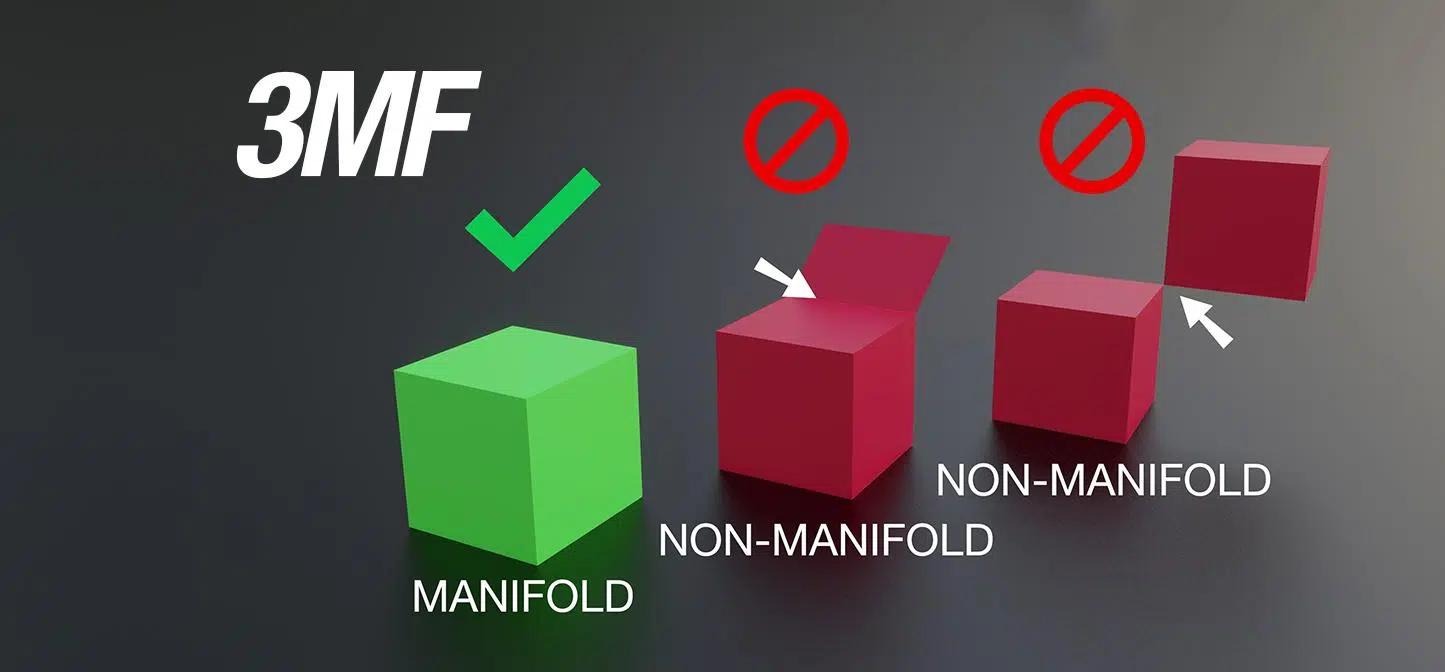
Choosing between STEP, STL, and 3MF files might seem like a minor detail, but it directly affects the quality, file size, compatibility, and even the errors you'll encounter in 3D printing. The same part can be printed in these formats with very different results: from a faceted mesh that reveals triangles on the surface to a "ready-to-print" container with predefined materials, textures, and supports.
In this guide, I explain, with a practical and technical approach, the real differences between STEP, STL, and 3MF (and where OBJ and AMF fit in), so you know when to use each one, what limitations they have, and how to avoid common problems such as corrupted files , non-manifolds, or loss of detail due to triangulation. All of this is supported by key information shared by industry players and specialized communities.
From CAD to Printer: How STEP, STL, and 3MF Fit into Your Workflow
Additive manufacturing begins in CAD and ends with the printer executing G-code, but in between is the slicer, which doesn't work directly with parametric formats like STEP/IGES or native formats like IPT or SLDPRT. The slicer needs a mesh suitable for manufacturing; therefore, it's exported or converted to "printing" formats like STL, OBJ, AMF, or 3MF before generating the G-code.
Slicing divides the model into layers and creates motion and deposition instructions (G-code) for the machine to build the part layer by layer. In this process, the critical data are the geometry and, increasingly, color, texture, material, orientations, and even metadata and print profiles—information that not all formats can store.
Some manufacturers offer native slicers that directly accept certain formats and simplify the process, but in general, STEP files don't go to the slicer without prior conversion. This explains why, although STEP is king in design and engineering, STL and 3MF are the preferred formats near the printer.
In practice, the typical workflow is: design in CAD (parametric) → export/convert to a print format → laminate → send G-code to the printer. Understanding what each format stores saves you iterations, rework, and surprises in surface finishes or materials.
STL: The universal mesh that prints everything (with its drawbacks)

STL (Stereolithography or Standard Tessellation Triangle Language) is the most compatible veteran format: it represents the surface as a network of triangles that approximate the model. The more triangles, the better the curves are approximated and the smoother the resulting piece, at the cost of increasing the file size.
Its simplicity is both its strength and its limitation: STL only stores surface geometry, without color, textures, materials, or explicit scale. This is usually sufficient for single-material prototypes and simple parts, but it falls short with multi-color/multi-material technologies.
STL files can be ASCII (readable, larger) or binary (compact and efficient), with the latter being more practical for working and sharing. Tools like Meshmixer, MeshLab, or Netfabb are often used to debug and optimize these meshes.
Common rules and best practices: normals should point outwards (consistent orientation), triangles should share vertices correctly, and the mesh should be watertight and manifold. Some workflows impose additional conventions, such as maintaining positive coordinates or ordering triangles to facilitate processing, but these are not part of the formal STL standard.
A known drawback: with high-resolution processes (e.g., HP Multi Jet Fusion), facets may be visible if the triangulation density is low. This is the typical "the triangles are showing" effect, a symptom of overly loose export tolerances or aggressive simplifications.
OBJ and AMF: Two alternatives that add color and detail
OBJ, originally developed for computer graphics, is a neutral and simple format that, unlike STL, supports colors and textures via an .mtl file (and associated .png textures). Furthermore, it can represent geometry with polygons and quadrilaterals, and even freeform surfaces, improving fidelity.
An OBJ project typically consists of several parts: the .obj file containing the geometry and the .mtl file containing the materials; you can include multiple objects in a single file. This makes it very useful when you need to exchange models with visual attributes between applications.
AMF (Additive Manufacturing File Format), promoted by ASTM F42, is an open standard that uses XML and allows geometry, colors, textures, and multiple objects in a single file. It is designed to accurately describe the part (including detailed meshes and finer surface rendering), and can even handle concepts such as grids or voxels.
Although AMF was introduced to overcome the limitations of STL, its adoption has been slower than that of 3MF, despite its technical advantages and native focus on additive manufacturing. Even so, it's a solid option if your software and workflow support it.
3MF: The container designed to print, share, and not fail

3MF (3D Manufacturing Format) was created by the 3MF consortium (originally led by Microsoft, with members such as Autodesk, Dassault Systèmes, Stratasys, Ultimaker, and others) to go beyond STL and AMF. It is open, XML-based, and designed specifically for modern 3D printing.
It works like a compressed container (ZIP type): in fact, you can rename the extension to .zip and view its contents, which facilitates debugging, human readability, and extensibility. Inside, the mesh is stored, and, above all, scene and fabrication information that other formats don't include.
What can 3MF include? Materials, colors, textures, correct scene units, thumbnails, multiple parts in the same scene, and—crucially—the slicer configuration: printer profiles, manual supports, variable layer heights, and modifiers. This allows you to share "ready-to-print" projects with everything fine-tuned.
Another powerful advantage is instantiation: you can reference the same object multiple times without duplicating the mesh, saving space and reducing errors; furthermore, it clearly defines multiplicity and avoids non-manifold ambiguities. This is why 3MF typically produces fewer errors and more compact files than an equivalent STL.
3MF is well supported by popular slicers (PrusaSlicer uses it as its default project format, and it's supported by Cura, Simplify3D, IdeaMaker, and others), although interoperability limitations still exist between programs for advanced printing parameters. Even so, the model and many settings transfer more smoothly than with previous alternatives.
STEP: The exact CAD standard to convert for printing
STEP (STP, Standard for the Exchange of Product Model Data) is an ISO standard for exchanging product model data; it stores exact geometry and design with mathematical precision. It is ideal for engineering, parametric design, and complex assemblies, and enjoys broad compatibility among CAD tools.
STEP files can divide information into modules and be saved in ASCII (human-readable) or binary, and are designed for portability between systems without loss of design intent. Their neutrality and interoperability have made them a cornerstone of CAD exchange.
But for 3D printing, a STEP file must be converted to a mesh (triangulation) before entering the slicer; sending STEP files to a service allows them to control the triangulation density appropriate for the technology and finish. This prevents STL files from being exported incorrectly due to size limitations or poorly adjusted tolerances.
The reverse STL-to-STEP conversion is complicated because STL only contains mesh without history or parameters; the STEP-to-STL conversion is direct, although you can lose detail if you set tolerances that are too coarse. Choosing the right export method is key to avoiding unwanted facets.
Practical differences between STEP, STL and 3MF (when to use each one)
If your goal is to design and share with engineering, STEP is the "source" format that preserves intent and precision; you won't use it directly for printing, but it's the best starting point. It allows the manufacturer to determine the optimal triangulation based on the process and surface requirements.
If you want to control the mesh yourself and send something lightweight and universal, STL remains the fast and compatible option for simple, single-material parts. You'll decide the resolution/size balance, with the drawback of not including color or parameters.
If you're looking to maintain control and metadata without worrying about file size, 3MF lets you package geometry, materials, and the entire project configuration into a single print-ready file. It's the most convenient and robust way to share complex projects.
A helpful way to think about it: with STEP you delegate triangulation to the manufacturer; with STL you control it, but you're limited by size; with 3MF you control it and, in addition, share the entire printing context without so many weight restrictions. This way you align quality, reproducibility, and collaboration.
OBJ and AMF in context: When do they come into play?
OBJ is practical when color/texture mapping matters and you're working between 3D apps and slicers; remember to include the .mtl file and textures so the material isn't lost. It's versatile, but managing multiple associated files can be less convenient than a single 3MF file.
AMF shares with 3MF the XML base and the ability to handle multiple materials, colors, and higher surface accuracy, with the advantage of being an ASTM-designed standard for printing. If your ecosystem supports it well, it's technically very capable, although less popular.
Size, resolution, and quality: how to avoid overshooting the weight or losing detail
More triangles mean higher fidelity and smoother surfaces, but also larger files and more processing demands on the slicer. Adjust the export tolerances in CAD (chord height and angular tolerance) so the mesh is as fine as you need, without going overboard.
As a general guideline, it's recommended to keep the chord height small relative to the key dimensions and maintain a reasonable angular tolerance; some references suggest values on the order of a fraction of the surface area (e.g., 1/20) and angles around 15°, depending on complexity. This isn't a rigid rule, but rather a starting point for iteration.
To reduce file size without compromising the model's integrity, use controlled mesh simplification (Reduce/Simplify in tools like Meshmixer) and consider using 3MF, which compresses and encapsulates better than STL. This allows you to maintain fine geometry with more manageable files.
When scaling models, do so proportionally and ensure they still fit within the build volume and meet functional tolerances if they are to be assembled with other parts. Aggressive reductions can erase critical details and ruin fits.
3MF Advantages in Collaboration and Repeatability
Sharing a 3mf file from a slicer (e.g., PrusaSlicer) allows you to package profiles, manual supports, variable heights, modifiers, orientation, materials, and thumbnails along with the mesh. The recipient will start from your same project state, without needing to reconfigure it.
For external services, sending 3MF reduces misunderstandings and errors: they not only see the part, but also how you intended to print it and why. This avoids iterations and speeds up production times, especially for models with fine details or highly customized supports.
Some platforms and model catalogs are beginning to accept 3MF for distributing complete "printable projects," including licenses and metadata. Unlike STL, which is only the mesh, 3MF preserves context and rights within the file.
Interoperability between slicers isn't yet perfect for advanced parameters, but 3MF, being open and XML-based, is being expanded and standardized with the support of the consortium and key players. It's a forward-looking approach with clear benefits already being seen today.

Passionate writer about the world of bytes and technology in general. I love sharing my knowledge through writing, and that's what I'll do on this blog, show you all the most interesting things about gadgets, software, hardware, tech trends, and more. My goal is to help you navigate the digital world in a simple and entertaining way.