- Hardware configuration and control parameters using Startdrive and technological positioning objects.
- Implementation of axis control using pulse take-offs (PTOs) for efficient solutions in S7-1200.
- Managing complex movements through Motion Control instructions and sequential command tables.

Entering the world of industrial automation might seem daunting at first, but mastering servo motor control with TIA Portal is a game-changer for any technician. We're not talking about simple motors that rotate, but systems capable of moving with pinpoint accuracy , controlling speed and acceleration in detail so the machine does exactly what we want.
To achieve this, Siemens offers a powerful ecosystem where the PLC acts as the brain and the servo controller as the muscle. Depending on whether we use an S7-1200 or an S7-1500, the programming strategy will change slightly, as some allow pulse control and others manage much more complex digital communications through technological devices.
Servo Configuration with the S7-1500 and SINAMICS S210
When we work with high-end systems like the S7-1500 (especially the T-series CPUs), things get interesting. These systems are designed to coordinate complex movements. The process begins by integrating the hardware and software in TIA Portal , where we configure the PLC, servo controller, and motor to communicate with each other.
A key component is the use of Startdrive , the specific tool for parameterizing servomotors. This is where we adjust the general data and evaluate the system's response to ensure smooth movement and flawless position control. Communication typically flows via PROFINET or PROFIBUS , allowing the PLC to send precise data to the motor controller.
Axis Control via Pulse Output Terminal (PTO) in S7-1200

If you don't have a very large budget or the task is simpler, the S7-1200 is a fantastic ally thanks to its Pulse Train Output (PTO) . This is a very efficient option for positioning axes without overcomplicating things. Keep in mind that to use this, the PLC must have transistor (PNP) outputs , typically DC/DC/DC models.
Depending on how we configure the system, we can use pulse and direction mode (where one output indicates the speed and another the direction of rotation) or bi-phase pulses. It is vital to monitor the maximum output frequencies, which can range from 20 kHz up to 1 MHz in models like the 1217C, as this defines the motor's maximum response speed.
The Technological Positioning Object
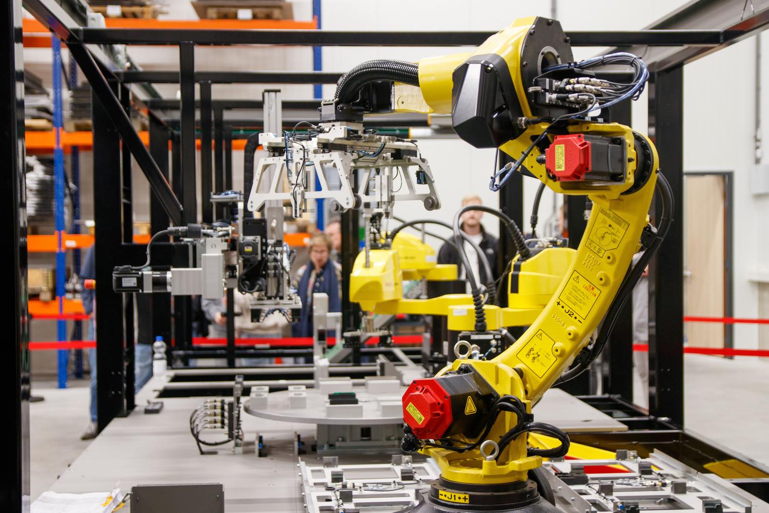
To avoid having to program each pulse manually, TIA Portal provides the (TO_PositioningAxis) technology objects . These wizards guide us through configuring the axis, allowing us to choose between open-loop (PTO) or closed-loop control. We can define the unit of measurement , either millimeters for linear axes or degrees for rotary axes.
In the mechanical configuration, we tell the PLC how many pulses per revolution the motor has and what the linear advance is. This is also the time to set the position limits , both through software and physical limit switches, to prevent the motor from crashing into something and causing a disaster.
System Dynamics and Referencing

It's not enough for the motor to simply move; we need to define how it moves . In the dynamic settings, we configure speeds, accelerations, and jerk limitation to ensure smooth movement. Furthermore, we must plan for emergency stops to guarantee the safety of the installation.
A critical point is homing . Since there is no real feedback in PTO mode, the PLC doesn't know the motor's location when it starts. That's why we use the MC_Home instruction . There are several modes, from direct absolute homing to active homing (Mode 3), where the axis moves automatically until it finds the home sensor.
Motion Control Instructions and Command Tables

To move the axis in the program, we use specific function blocks. The basic ones are MC_Power to energize the motor, MC_Reset to clear errors, and the motion blocks MC_MoveAbsolute and MC_MoveRelative . Each of these instructions intelligently manages the servo's path.
If the sequence of movements is very complex, it's best to use the TO_CommandTable . This allows us to create a list of up to 32 steps in a graphical environment. We can choose between closing the request (where the motor brakes and then accelerates again) or smoothing the movement , which makes the transition between steps fluid, reducing mechanical wear and saving cycle time.
Implementing these systems requires a logical workflow that extends from physical cabling and network configuration to commissioning using jog functions and manual positioning. By properly integrating communication telegrams and technological devices, we achieve complete control over industrial machinery, optimizing the productivity and accuracy of any automated process.
