- The commands AutoCAD allows you to draw, edit, dimension, and manage blocks and views with maximum speed from the keyboard.
- Mastering basic aliases like LINE, CIRCLE, MOVE, ERASE, or ZOOM greatly speeds up daily 2D work.
- Advanced commands such as EXTRUSION, SUPERFJOINT or XLINK enhance 3D modeling and project coordination.
- Configuring custom selection options, styles, and shortcuts increases accuracy and productivity in any project.
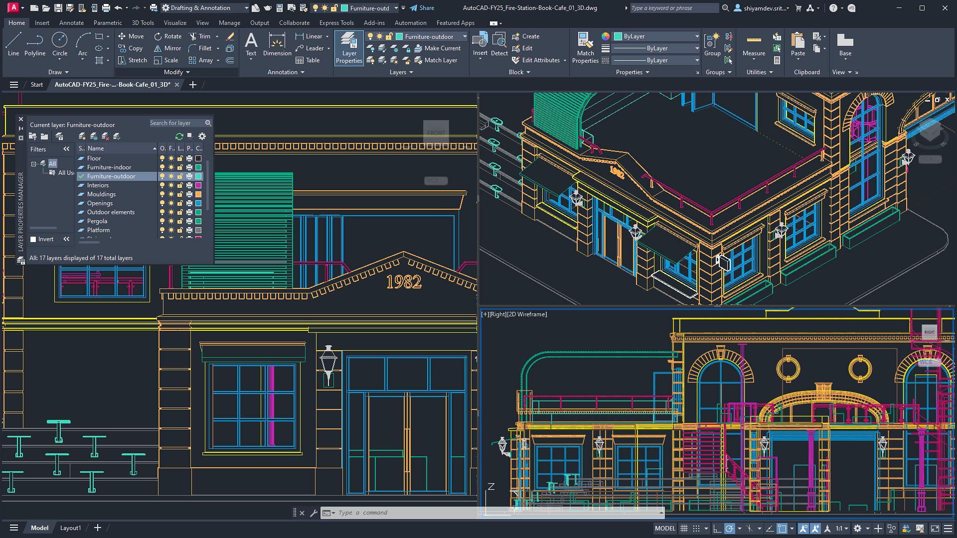
Mastering AutoCAD commands makes all the difference between haphazard drawing and a streamlined, professional workflow. When you get used to typing commands in the command bar instead of searching through menus, you start saving minutes on every task—minutes that add up to hours saved by the end of the day.
Furthermore, many AutoCAD commands have English names, short aliases, and Spanish equivalents , which can sometimes be confusing for beginners. This comprehensive guide provides a complete and organized collection of basic and advanced commands, with clear explanations and usage examples to ensure you don't miss a thing.
What are AutoCAD commands and why are they so important?
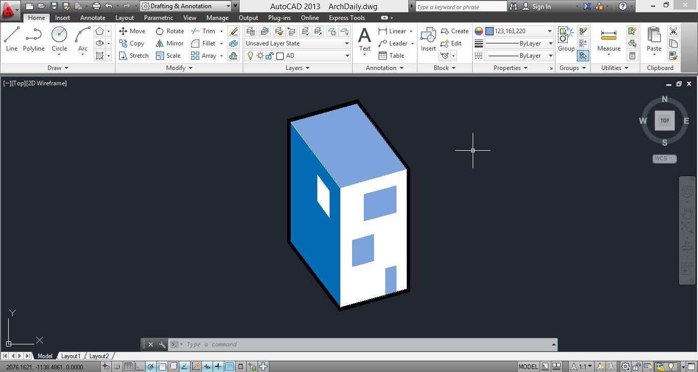
In AutoCAD, a command is an instruction you type on the command line (or activate from a button) to make the program perform a specific action: draw, delete, move, change space, manage views, etc. It's the most direct way to tell the software what you want it to do.
When you rely solely on menus and the ribbon, you waste time navigating between tabs and panels , or you don't know how to display a toolbar in AutoCAD . However, if you learn the command names or aliases, you can type two letters, press Enter, and immediately start working on the drawing without taking your eyes off the screen.
Another key advantage is that many commands support powerful parameters, options, and selection modes . This allows you to fine-tune the result (for example, choosing how to scale, extrude, or select objects) much more effectively than if you only use visual shortcuts.
Benefits of using commands in AutoCAD versus working only with icons
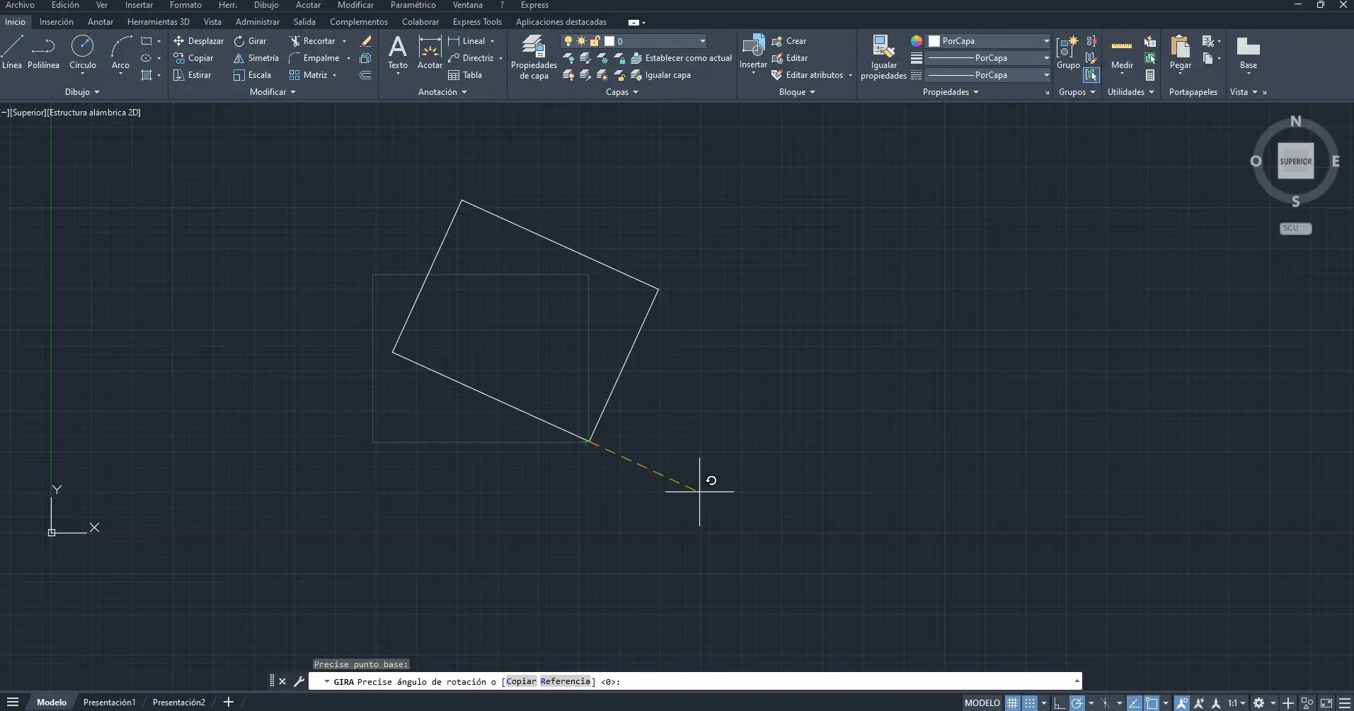
One of the biggest benefits of using keyboard shortcuts and commands in AutoCAD is speed: once you memorize the most important ones, drawing and editing become much smoother. You barely lift your hand from the keyboard and minimize unnecessary clicks.
You also gain in precision, because the command line guides you with clear messages : it asks for points, distances, angles, objects to select, and additional options. By following these instructions, it's harder to make mistakes by clicking in the wrong place.
It's important to remember that AutoCAD allows you to customize aliases and shortcuts . If you use a command frequently, you can assign it a very short abbreviation to activate it almost instantly. This is key to adapting the program to your workflow.
Finally, when learning commands, it becomes much easier to follow tutorials, manuals, and technical documentation , since most professional resources are based precisely on the use of these names and aliases, usually in English.
List of basic AutoCAD commands you should master
The basic commands are the core of your daily work in AutoCAD. With them, you draw the main geometries, edit them, add dimensions, create blocks, and prepare drawings for printing. Below you'll find a list organized by action type so you can clearly understand the purpose of each group.
1. Fundamental drawing commands
In the drawing section you will find the commands that create the basic 2D geometric entities , which you will use in practically all your projects, from a simple sketch to an executive plan.
- A – ARC (ARC): Creates circular arcs. You can define them by three points, by center and radius, by start and angle, etc. It's useful for fillets, smooth curves, and details. To measure arcs, see How to measure the length of an arc in AutoCAD.
- C – CIRCLE (CIRCLE): Draws circles by specifying center and radius, center and diameter, or other combinations. It is an essential command for any type of design.
- L – LINE (LINE): Generates straight line segments, linking one point to another. It is the basic command for creating simple 2D geometry and is usually one of the first commands learned.
- H – HATCH (SHADING): applies shading or a pattern to a closed area. It is used to represent materials, sections, or to highlight specific areas of a plan.
- T – MTEXT (MULTI-TEXT): Creates multi-line text with an editing box. Allows control over style, height, justification, and formatting, ideal for long notes.
2. Essential Editing and Modification Commands
Once the objects are drawn, the editing commands allow you to correct, adjust, or transform the existing geometry . Many of these are located on the Home tab, in the Modify panel, but they can also be activated using aliases.
- E – ERASE (DELETE): Deletes the selected objects. You can select before or after executing the command, depending on your selection settings.
- M – MOVE (MOVE): moves one or more objects from a base point to a destination point. It is very useful for precisely repositioning elements.
- F – FILLET (FILLE): Creates a rounded corner between two segments or edges. Allows you to define a radius or even join lines without a radius, trimming their length.
- O – OFFSET (OFFSET): Generates parallel or concentric lines, arcs, or circles from an existing object, at a specified distance.
- J – JOIN (UNIR): Combines several collinear or contiguous segments, arcs, or objects into a single entity, provided they are compatible.
- S – STRETCH (STRETCH): modifies the shape of one or more objects by moving a part of them, usually by selecting with a crosshair. Very powerful for readjusting dimensions.
- X – EXPLODE (EXPOSE): ungroups compound objects (such as blocks or complex polylines) into simpler elements so they can be edited individually.
These editing commands can be applied to objects that are already selected, or you can execute the command first and then choose what you want to modify . AutoCAD allows for pre-selection (before the command) and post-selection.
3. Dimensioning commands and styles
To generate clear documentation, dimensions and text styles are essential . AutoCAD has specific commands to define how these annotations are displayed.
- D – DIMSTYLE (DIMENSION STYLE): Create and manage dimension styles. From here you decide arrow types, scale, text formatting, units, etc.
- EST – STYLEThis is used to create, modify, or set text styles. You can define fonts, sizes, and other parameters used in MTEXT or DTEXT.
- ESTDM – ESTILDIRECTRIZM: creates and edits multileader styles, which combine arrow, line and associated text.
- ETA – STYLOTABLE: manages table styles, defining the appearance of cells, borders, text, and alignments.
4. Commands for blocks and content management
Blocks are groups of objects that are reused in multiple parts of the drawing . They allow you to save a huge amount of time, maintain graphic consistency, and facilitate global changes.
- B-BLOCK (BLOCK): Creates a block definition from the selected objects. Once defined, you can insert it as many times as needed.
- I – INSERT (INSERT): Places a reference to an existing block in the drawing. Allows you to choose the insertion point, scale, and rotation.
- W – WBLOCK (WRITE BLOCK): Saves objects or an existing block to a separate DWG file. It is ideal for creating reusable libraries.
- EV – STATEBLOCK: creates, sets or suppresses visibility states in dynamic blocks, allowing you to show or hide parts of the block as needed.
- ESITU – EDITATRINSITU: modifies the textual content of an attribute within a block directly "in situ", without having to redefine it.
5. Visualization, views and navigation
Working comfortably in AutoCAD is not just about drawing, it's also about moving freely around the workspace, zooming in and out, and saving useful views to return to them when needed.
- P – PAN (FRAMING): shifts the view without changing the objects, as if you were moving the paper under a magnifying glass.
- Z – ZOOM: Changes the zoom level. You can zoom by window, by extent, dynamically, etc.
- R – REDRAW (REDRAW): regenerates the drawing display, correcting small graphic errors on screen.
- V – VIEW (VIEW): Saves and restores user-defined views, very practical in large projects for jumping between key areas.
- EVA – ESTVISACTUAL: sets the visual style of the current viewport (realistic, conceptual, wireframe, etc.), especially useful in 3D.
- EVIS – ESTILVISUAL: creates, modifies, and applies custom visual styles to viewports.
6. Workspaces, printing and saving
In a typical workflow, you draw in model space and render in paper space , preparing viewports, print scales, and saving the file in the appropriate format. If you work with online images, see how to remove frames and borders in AutoCAD.
- EP – ESPACIOP: While in a layout, it switches from model space within the viewport to paper space and vice versa.
- Q – QSAVE (QUICK SAVE): Saves the current drawing without displaying the dialog box, using the existing name and path.
- EX – EXPORT: allows saving the drawing content in other file formats (for example, to exchange with other programs).
Advanced AutoCAD commands worth trying
Once you've mastered the basic commands , it's time to go a step further and take advantage of advanced tools for 3D modeling, surfaces, coordination with other models, and external reference management. This is where AutoCAD becomes especially powerful for professional architecture and engineering work.
1. 3D modeling and surfaces
In the three-dimensional realm, AutoCAD includes specific commands for creating solids, surfaces, and meshes . These are some of the most prominent ones within the content you've viewed.
- EXT – EXTRUSION (EXTRUSION): Generates a 3D solid from an entity that encloses an area (such as a closed polyline) or creates a 3D surface from an open boundary. It is the basis of simple volumetric modeling.
- EMPA – SUPERF EMPAL: creates a splice surface between two existing surfaces, smoothing the transition between them.
- FUSI – SUPERFUSE: produces a continuous bonding surface between already created surfaces, achieving a link without visible jumps.
- ESCU – ESCULPESUPERF: Starting from surfaces or meshes that completely enclose a volume, cut and combine the set to obtain a resulting 3D solid.
These commands are widely used in organic modeling or in parts with complex shapes , where simple extrusions are not enough and you need smooth transitions or sculpted volumes.
2. Links, external references and model coordination
In larger projects, it's common to work with multiple files, point clouds, or models from other programs (such as Navisworks). AutoCAD offers specific commands to manage these references without having to embed everything in a single DWG file; it's also common to convert images to DWG to integrate them into the workflow.
- ENLA – ENLAZARNUBUNTOS: Inserts a point cloud (RCS file) or a point cloud project file (RCP) into the current drawing. Widely used for working with laser scans.
- ENLAZARMC – ENLAZARMODELOCOORDINACION: incorporates coordination models into the drawing, such as Navisworks NWD and NWC files, allowing interference checks and discipline coordination.
- ENX – LINK: links other DWG files as external references (Xrefs). This allows you to split a project into multiple files while maintaining consistency between them.
By using these external references, your main file remains lighter and, at the same time, you can work with information from other teams, scans, or coordination models without duplicating data.
3. Coordinate system and location tools
When managing complex projects, you often need to control custom coordinate systems or access geographic location information for the drawing. Several commands can make this task easier.
- UC – ADMINSCPIt manages user-defined personal coordinate systems (PCS). It allows you to create, rename, and manage different work orientations.
- N – NORTH: provides information about the location or north orientation of a drawing file, which is useful for topographic or site plans.
4. Visual styles and visibility states
In addition to modeling and referencing, it is essential to control how objects are displayed on screen , both for comfortable work and for preparing presentation views or captures.
- EVA – ESTVISACTUAL: directly select the active visual style in the graphics window you are working in.
- EVIS – ESTILVISUAL: It is used to create and adjust visual styles (for example, with highlighted edges, shadows, materials, etc.) and assign them to one or more windows.
- EV – STATEBLOCK: already mentioned in blocks, but key here too, as it controls which parts of a dynamic block are seen or hidden.
Editing commands in the Modify tab: how they work and how they select objects
Within the Home tab, you'll find the Modify panel , which groups together many of the editing commands already mentioned: ERASE, MOVE, FILLET, OFFSET, STRETCH, etc. The workflow is simple: first, you select what you want to change, and then you decide how you're going to modify it.
In AutoCAD, object selection can be done before or after issuing the command . If you run, for example, MOVE with nothing selected, the program will prompt you to select now. If, however, you already had items selected, the command will apply to that previous selection.
There is also a configuration option called Noun/Verb Selection , located on the Selection tab of the Options dialog box. If this option is disabled, AutoCAD ignores the previous selection when you issue an edit command and always prompts you to reselect the objects, which significantly changes your workflow.
When noun/verb selection is disabled, even the Delete key stops working to delete preselected objects , because the program doesn't accept that selection "before the verb." To change this, simply go to Options, check the corresponding box, and you'll have the usual preselection functionality again.
AutoCAD command guide with basic keyboard shortcuts
To truly get the most out of AutoCAD, it's helpful to memorize the shorter aliases of the most frequently used commands . This way, instead of typing the full name or searching for the icon on the ribbon, you can simply type one or two letters and press Enter or the spacebar.
Many of the listed commands already have single-letter aliases : L for LINE, C for CIRCLE, M for MOVE, E for ERASE, Z for ZOOM, P for PAN, H for HATCH, etc. Others are named the same as their short alias: ARC, BLOCK, GROUP, OFFSET…
In the current version of AutoCAD (for example, AutoCAD 2023 and later), this method remains perfectly valid and, in fact, is preferred by advanced users and highly experienced drafters . The mouse is primarily used to pinpoint locations, not for constantly navigating through menus.
If you wish, you can customize or add your own aliases using the command definition file or customization tools , thus adapting AutoCAD to your preferences. For example, you can make "LL" activate LINE, or "RR" launch ROTATE, if that's more convenient for you.
Practical tips to improve your efficiency with AutoCAD commands
Beyond memorizing names, it's important to apply a series of tricks and best practices to make the most of the command line and gain fluency in everyday use.
- Combine pre-selection and post-selectionGet used to alternating between selecting objects before and after executing the command, depending on what's faster in each situation, and organize elements with Layers in AutoCAD.
- Use the Function keysF8, for example, activates/deactivates ORTHO and together with FORZCURSOR (FC) you can better control the cursor direction.
- Activate ForzCursor (FC – FORZCURSOR): limits cursor movement to set angular intervals or directions, which helps to draw cleaner and align correctly.
- Get the most out of FILTER (FI – FILTER)It creates complex selection filters, specifying which properties the objects you want to select must have (layer, line type, color, etc.). It's ideal for modifying large sets of objects without having to click on them one by one.
- Maintain consistent stylesKeep your text styles, dimensions, tables, and leaders (EST, DIMSTYLE, ESTILOTABLA, ESTILDIRECTRIZM) properly configured so you don't waste time correcting annotations later.
Also, don't forget to use VIEW (V – VIEW) to save typical views of your project (general plan, detail of a specific area, etc.). This saves you a lot of time zooming and framing every time you need to return to a part of the plan.
How to use AutoCAD commands step by step from the command line
The general procedure for working with commands in AutoCAD is very simple, although it is advisable to internalize the basic sequence so that it comes out almost automatically every time you want to do something.
- Enter the alias or command name on the command line (for example, L for LINE, M for MOVE, H for HATCH) and press Enter or the space bar.
- Follow the instructions that appear on the command lineThe program will ask you for points, distances, angles, object selection, or alternative options.
- Use the options that appear in brackets (for example,) typing the highlighted letter and pressing Enter to activate them.
- Confirm or cancel the command Pressing Enter when you no longer want to enter any more data, or pressing Esc to exit if you have made a mistake.
With this approach, you end up working almost without looking at the keyboard . Your focus is on the drawing, you read the contextual instructions, and you respond quickly with the keyboard, which greatly increases your productivity.
AutoCAD also keeps a recent history of commands, so you can repeat the last one used simply by pressing Enter or the space bar , which is especially useful if you are doing repetitive tasks (for example, several successive lines or multiple displacements).
By mastering this list of commands and their variants, along with the management of selections, styles, and references, your way of working with AutoCAD becomes much more fluid, organized, and professional , both in 2D and 3D, whether for basic drafting or for complex projects coordinated with other teams.


Passionate writer about the world of bytes and technology in general. I love sharing my knowledge through writing, and that's what I'll do on this blog, show you all the most interesting things about gadgets, software, hardware, tech trends, and more. My goal is to help you navigate the digital world in a simple and entertaining way.