- VLANs allow logical segmentation of the network over the same physical infrastructure using 802.1Q.
- NIC Teaming and bonding add multiple interfaces to gain redundancy and bandwidth.
- Switches and servers must match in aggregation modes, allowed VLANs, and trunk configuration.
- VTP and EtherChannel facilitate centralized management and link aggregation in medium and large networks.
If you work with physical servers and managed switches or virtualized environments, sooner or later you'll have to grapple with VLANs, link aggregation, and NIC teaming . And yes, at first it sounds like gibberish, but once you understand how the pieces fit together, it becomes an incredibly powerful tool for improving performance, high availability, and network organization.
In this guide, we'll weave together all the theory and practice surrounding VLAN and teaming configuration in Windows, Hyper-V, VMware , and Linux , linking it to network design concepts (trunks, VTP, 802.1Q, EtherChannel, etc.). The goal is to give you a comprehensive overview: from what a VLAN is to how to create NIC teams via a graphical interface or PowerShell, how to do something similar in VMware, and how to configure bonding at a low level in Linux.
What are VLANs and why are they combined with NIC Teaming?
A VLAN (Virtual LAN) is essentially a way to create multiple logical networks over the same physical infrastructure , for example, to configure a DMZ . This allows you to have equipment in different rooms, and even on different switches, as if they were all on the same local network, without needing to run new cabling for each segment.
In more sophisticated networks, a three-layer architecture is typically used: access, distribution, and core . Access switches connect PCs, printers, and other devices; distribution switches aggregate traffic from multiple access switches; and core switches interconnect these distribution switches and are located near the router or outbound firewall.
VLANs are defined on switches, which must support IEEE 802.1Q as the labeling standard . Each switch port can be configured as an access port (belonging to a single VLAN) or a trunk port, which carries traffic from multiple VLANs simultaneously between switches or to hosts that understand VLANs (servers, routers, hypervisors, etc.).
When we combine VLAN with NIC Teaming, we enable a server to have multiple aggregated physical links (more bandwidth and redundancy) and, at the same time, we can separate traffic by VLAN (management, storage, production, backup, etc.) using tagged VLAN IDs on that NIC equipment.
NIC Teaming, Link Aggregation, EtherChannel and team modes
NIC teaming, also called link aggregation, bonding, or EtherChannel depending on the platform, is the technique of grouping multiple network interfaces into a single logical interface. This is done to increase effective throughput or provide fault tolerance (or both).
A typical scenario would be a server with two or more physical network cards, where the goal is that if one fails or someone disconnects a cable, traffic continues to flow without the user noticing . This is also used to aggregate bandwidth: for example, three 100 Mbit/s links combined can offer up to 300 Mbit/s total logical bandwidth, although the allocation is done per stream.
The main types or modes of network equipment are usually very similar across manufacturers. For example, many Broadcom adapters feature modes like Smart Load Balancing (SLB) with failover , where all traffic is distributed among several primary adapters, and if one fails, another takes over without any apparent interruption.
There is also SLB with backlink disablement, in which traffic does not automatically return to the original adapter when it recovers, which is useful for avoiding constant route changes . Other modes are based on standards such as IEEE 802.3ad/802.1ax (LACP), which create a logical link between several physical ports of the switch and the server, provided the switch is correctly configured for this purpose.
Finally, we have static aggregation mode , or "generic trunk ," which works very similarly to LACP, but without auto-negotiation. In this case, both the switch and the server must be manually configured so that the ports are part of the same aggregation group.
Configuring NIC Teaming with VLANs in Windows Server (GUI)
In Windows Server (2012 and later), you can use the built-in Microsoft NIC Teaming feature without relying on card manufacturer software. This greatly simplifies deployment, especially in Hyper-V environments.
Imagine two servers with multiple NICs: a pair of 1 GbE ports for management and a pair of 10 GbE ports for iSCSI storage and virtual machine traffic. It's very common to want to use the 1 GbE ports for management and clustering , and reserve the 10 GbE ports for storage and high-availability VM interconnection.
Before making any changes in Windows, it is essential that the switch is configured to support VLANs and, if applicable, aggregation (static or LACP), correctly assigning the ports that connect to the server. Otherwise, the NIC equipment may be powered on, but traffic will not flow properly.
To configure NIC Teaming and a tagged VLAN in Windows Server using Server Manager, the typical flow is as follows:
- Open the server administratorIt usually appears pinned to the desktop or taskbar; if not, you can press Win + X and choose “Server Manager”.
- In the left panel, enter the section “Local server”, where the main properties of the equipment are shown.
- Locate the "NIC Teaming" section. If it's listed as "Disabled," click on that text to launch the wizard. If you don't see the section, a role like Hyper-V might be missing, or you might be using an edition that doesn't support it.
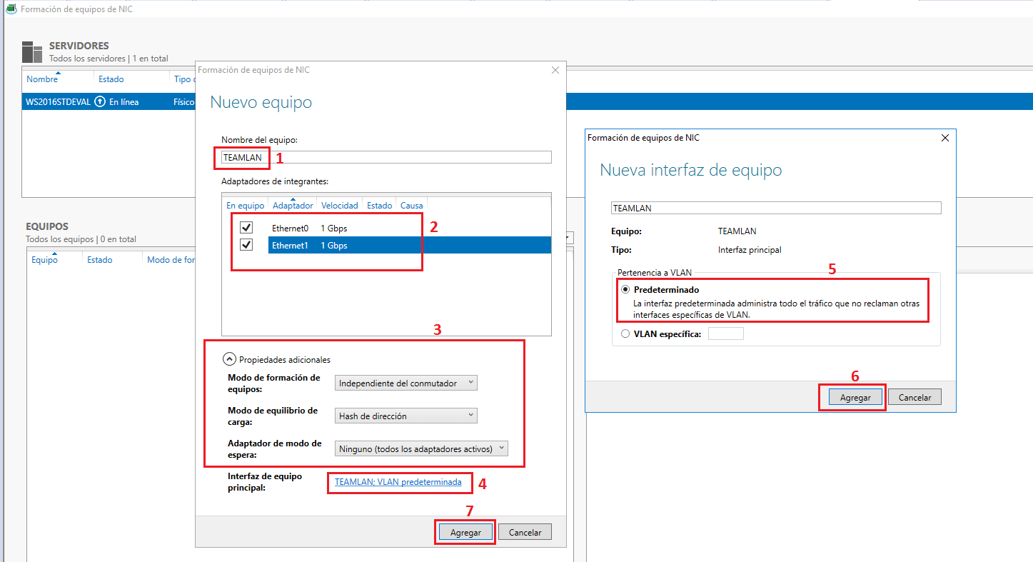
In the NIC teaming window, you'll see a list of available physical adapters . From there, you can create a new team by following these steps:
- Select the NICs you want to add in the “Adapters and Interfaces” panel.
- Click on “TASKS” and then on “Add to new team”. The team creation dialog will open.
- Give the team a descriptive name, for example, “TEAM_10G” or “TEAMLAN”, to easily identify its function.
- If needed, expand the “Additional Properties” to choose the teaming modeThe load balancing mode and whether spare adapters will be available. In modern environments, the "Dynamic" balancing mode is usually recommended.
In this same dialog box, you can configure VLAN membership. Next to the main device interface , you'll see a link that allows you to create a new logical interface associated with a specific VLAN.
To define a tagged VLAN:
- Open the "New Team Interface" dialog box.
- Select “Specific VLAN” and enter the VLAN ID that corresponds (the same one you have configured on the switch).
- Confirm with Accept to generate the virtual interface associated with that VLAN.
Once the device interface and VLAN have been created, you must go to the Network Connections section of the server (Control Panel > Network and Internet > Network Connections, or from Settings > Change adapter options) and you will see the new logical adapter corresponding to the device (and, if applicable, to the VLAN).
On that VLAN adapter (not the physical NICs), you need to configure the IP address, subnet mask, gateway, and DNS . Right-click, go to Properties, locate "Internet Protocol Version 4 (TCP/IPv4)," and define the appropriate parameters for that virtual network. Repeat the process on the second server if you are setting up a redundant environment.
As a basic check, verify that the servers can ping each other across the VLAN . If there is no connectivity, review the VLAN and teaming configuration on both the server and the switch.
NIC Teaming in Windows Server by PowerShell
In addition to the graphical interface, Windows offers a very convenient cmdlet for creating NIC teams: the New-NetLbfoTeam command . This is especially useful when you want to automate deployments or document the configuration in scripts.
To use it, first open a PowerShell session with administrator privileges . You can search for “PowerShell” from the Start menu, right-click on Windows PowerShell, and select “Run as administrator.” If User Account Control asks for confirmation, accept.
The basic command to create a network device has this form:
New-NetLbfoTeam NOMBRE_DEL_EQUIPO "NIC1" , "NIC2"
Where you specify the name of the new logical team and the physical interfaces that will be members of it. For example:
New-NetLbfoTeam NIC-Team "NIC1" , "NIC2"
Once created, you'll find the new team interface in your network connections, just as if you had created it from Server Manager. From there, you can create additional VLANs if your driver and Windows version support it, or let Hyper-V manage the VLANs through the virtual switch.
NIC Teaming and Hyper-V: Management networks, storage, and VMs
On hosts running Hyper-V, it's common to separate traffic across several networks: host management, high-availability cluster, iSCSI storage, and VM production networks . VLANs and teaming play a key role here.
A typical configuration would be:
- 1 GbE NICs without tagging or with a dedicated VLAN for Host and domain management.
- 10 GbE NICs aggregated in one device, with multiple VLANs for iSCSI storage, Live Migration traffic, and VM networking.
- Using SET (Switch Embedded Teaming) in modern versions of Windows Server to group NICs at the Hyper-V virtual switch level, instead of using only classic NIC Teaming.
It is important that the host configuration matches the physical switch configuration: if you designate an interface on the host as a trunk with multiple VLANs, the corresponding switch port must be in 802.1Q trunk mode and allow those same VLANs . Any discrepancy in the list of authorized VLANs between the two sides will cause seemingly random connectivity drops.
NIC Teaming in VMware vSphere
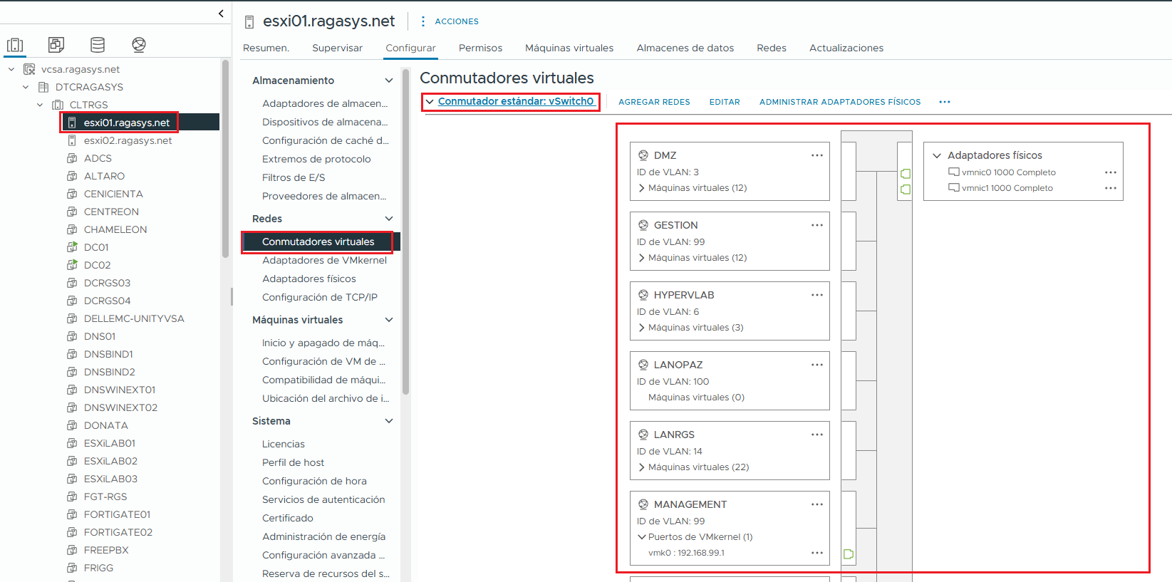
In VMware vSphere (ESXi) environments, the concept is similar, but the terminology changes slightly. There, you work with standard or distributed vSwitches , port groups, and load balancing and failover policies.
A network interface card (NIC) team in ESXi allows you to distribute traffic load across multiple physical adapters on the host and establish a failover order. This behavior is configured at the virtual switch or port group level, where you define which NICs are active, which are on standby, and which load balancing algorithm is applied.
Typical load balancing policies include:
- “Route based on originating virtual port.”
- “Route based on IP hash” (IP hash, which requires aggregation configuration on the physical switch).
- “Route based on source MAC hash”.
VMware provides step-by-step documentation on how to configure NIC teaming, failover, and load balancing on both standard and distributed switches. The classic reference is the knowledge base article on "NIC Teaming in ESXi and ESX," which also details the specific requirements for each ESXi version.
Bonding and aggregation in Linux (channel bonding)
In Linux systems, the functionality equivalent to NIC Teaming is usually called bonding or “channel bonding”. It is implemented through a kernel module that allows two or more physical interfaces to behave as a single logical interface (bond0, bond1, etc.).
Bonding offers both increased bandwidth and redundancy, but there are important nuances: some modes do not require configuration on the switch, while others do require the switch to be configured with features such as EtherChannel, LACP, or other types of link aggregation.
Among the most common modes we have:
- Active backup: one link active and the rest on standby, with no necessary changes to the switch.
- Balance-TLB (Transmit Load Balancing) and balance-ALB (Adaptive Load Balancing): distribute traffic without requiring special configuration on the switch.
- Aggregation-based modes (e.g., mode 0, 2, 3, and 4), which do require EtherChannel and, in some cases, LACP on the switch (depending on whether it's Cisco or another manufacturer).
To use bonding in distributions like Red Hat Enterprise Linux 6, you first need to load the kernel module:
modprobe --first-time bonding
If the module wasn't loaded, the command will activate it without displaying much on the screen. You can check its presence and parameters with modinfo bondingNormally, the upload is done automatically when the configuration files are detected. ifcfg-bondN with the appropriate directive.
The classic configuration is done in /etc/sysconfig/network-scripts/To create, for example, bond0, you generate an ifcfg-bond0 file with content similar to:
DEVICE=bond0
IPADDR=192.168.1.1
NETMASK=255.255.255.0
ONBOOT=yes
BOOTPROTO=none
USERCTL=no
NM_CONTROLLED=no
BONDING_OPTS="parámetros de bonding separados por espacios"
The physical interfaces to be added to the bond (for example, eth0 and eth1) will each have their own ifcfg-ethX file where the directives MASTER=bond0 and SLAVE=yes are added . This indicates that these interfaces do not have their own IP address, but instead become part of the logical link.
Once the files have been created, you can restart the network service with service network restart and check the link status with:
cat /proc/net/bonding/bond0
This file displays the bonding mode, MII status, polling times, and which interfaces are active. If you need multiple bonds (bond0, bond1, etc.), you repeat the process by creating additional ifcfg-bondN files and assigning different groups of physical interfaces to each bond using MASTER=bondN.
Key VLAN concepts: access ports, trunks, and 802.1Q
Once you've mastered the world of teaming, it's time to understand the logic behind VLANs. The first requirement is having switches that support the 802.1Q standard for VLANs . Without that, you're out of luck. In Cisco, for example, you can define VLANs from 1 to 4094; 1 to 1005 are considered normal range, and 1006 to 4094 are considered extended range.
Normal-range VLANs are stored in the switch's flash memory in a vlan.dat file . VLANs 1 and 1002-1005 are created by default and cannot be deleted, as they are reserved for legacy functions (such as Token Ring and FDDI). Extended-range VLANs are stored in the running configuration and require the switch to be in VTP transparent mode if you want to manage them with VTP.
A port configured as "access" belongs to a single VLAN. This is typical for a PC, printer, or server without VLAN support . On the other hand, a trunk port carries frames from multiple VLANs tagged using 802.1Q. This type of link is used for traffic between switches, to routers with subinterfaces, or to servers that support tagged VLANs.
In 802.1Q, the Ethernet frame is minimally modified to add a VLAN ID field to the header . The order becomes: destination MAC, source MAC, VLAN label (which includes the identifier), and then the remaining fields. This identifier allows the switch to know which VLAN the frame belongs to when it arrives via a trunk.
Configure VLANs and ports on Cisco switches
In Cisco IOS, creating a VLAN is quite straightforward. In global configuration mode, you simply specify the VLAN number and a descriptive name to help you avoid getting lost in large networks.
The basic steps would be:
- Enter global configuration mode with configure the terminal.
- Create the VLAN with VLAN.
- Assign it a name with yam.
- Exit into privileged EXEC mode with end.
For example, to create VLAN 20 and name it “student”:
S1(config)# vlan 20
S1(config-vlan)# name student
S1(config-vlan)# end
Next, you need to associate ports with that VLAN. To do this, switch to interface configuration mode and set the port to access mode, assigning it to the desired VLAN.
Switch(config)# interface fa0/6
Switch(config-if)# switchport mode access
Switch(config-if)# switchport access vlan 20
Switch(config-if)# end
It's good practice to use `switchport mode access` to block the port as a fixed access point and prevent it from unexpectedly negotiating as a trunk with another device. You can view a summary of the created VLANs and the ports associated with each one using `show vlan brief`.
Voice and data VLAN on the same port
Although an access port can only belong to a data VLAN, many switches also allow you to assign an additional voice VLAN , which is very useful when you connect an IP phone and a PC behind it.
In Cisco, the typical configuration for a port that carries user data and VoIP would look something like this:
interface fa0/18
 switchport mode access
 switchport access vlan 20
 mls qos trust cos
 switchport voice vlan 150
With this, PC data will go through VLAN 20 and voice traffic through VLAN 150. The mls qos trust cos command tells the switch to trust the Class of Service (CoS) value indicated by the phone, so that appropriate Quality of Service policies can be applied to prioritize voice.
The result can be verified with show vlan brief or show interfaces fa0/18 switchport , where you will see the access VLAN, the trunk's native VLAN (if applicable), and the configured voice VLAN.
Modify or delete VLANs and port memberships
If a port has been assigned to the wrong VLAN, simply reapply the `switchport access vlan` command with the correct ID. If you want the port to return to the default VLAN (VLAN 1), you can use:
interface fa0/18
 no switchport access vlan
This command removes the specific assignment, so the port returns to VLAN 1 (as is usually verified with `show vlan brief` ). Note that the VLAN itself (for example, VLAN 20) will still exist even though it no longer has any associated ports.
To completely remove a VLAN from the switch, the following command is used in global configuration mode:
no vlan <vlan-id>
And if you want to clear the entire VLAN database (for example, to return the switch to its factory settings in that respect), you can delete the vlan.dat file from the flash memory with:
delete flash:vlan.dat
After restarting the switch, the defined VLANs will disappear, and you'll revert to the factory default VLAN configuration. Obviously, this command must be used with extreme caution, as it will erase all configured VLANs.
VTP and centralized VLAN management
In large networks, manually creating or renaming VLANs on each switch becomes a nightmare. That's where the VLAN Trunking Protocol (VTP) comes in , allowing VLAN information to be distributed among switches belonging to the same VTP domain.
VTP works with three main modes:
- Server: can create, modify and delete VLANs, and sends advertisements to the rest.
- Client: receives the VLAN database from servers, but you cannot edit it.
- Transparent: does not participate in the global database, but forwards VTP advertisements; maintains its VLANs locally.
The basic configuration in global mode includes:
- Define the domain with
vtp domain <nombre-dominio>. - Set the password with
vtp password <clave>. - Set the mode with
vtp mode serverovtp mode clientas per the touch. - Make sure that the Trunk links between switches are active so that VTP information can circulate.
Common VTP errors include poorly synchronized passwords, carelessly mismatched domains, or a switch in transparent mode that becomes the only path between network areas, causing certain VLAN names to not reach the rest of the devices.
EtherChannel, VLAN, and port aggregation on switches
EtherChannel is Cisco's implementation for grouping multiple physical ports into a single logical link , similar to NIC teaming on servers, but on the switch side. It supports VLANs and can operate in access or trunk mode, combining the bandwidth of the participating links.
The idea is that several ports (for example, Fa0/2, Fa0/3, and Fa0/4) behave as if they were a single port in the eyes of routing tables and Spanning Tree, preventing loops while increasing performance. The group is identified by a number (port-channel 1, port-channel 2, etc.).
To configure EtherChannel, you typically go into each physical interface and use something like:
interface range fa0/2 - 4
 channel-group 1 mode active
This will create a logical interface, Port-channel1 , on which you can then apply normal switch configuration (access mode, trunk mode, allowed VLANs, etc.). If the link needs to carry multiple VLANs, it's common practice to set the port-channel to trunk mode and list which VLANs are authorized.
For example, if you want the EtherChannel to carry only VLANs 100 and 200, you would enter the corresponding port-channel interface and execute something like:
interface port-channel1
 switchport mode trunk
 switchport trunk allowed vlan 100,200
It's important to be meticulous when selecting the interfaces that make up the EtherChannel; one of the most common causes of problems is including the wrong port. Often, the LED on that port will appear amber or behave erratically because it doesn't meet the requirements to be in the group.
Troubleshooting VLANs and network equipment
When something goes wrong in a network with VLANs, trunks, VTP, EtherChannel, and teaming, the cause is usually something simple that's hard to spot at first glance. It's a good idea to follow a checklist in order to avoid going crazy.
Some practical steps for diagnosing incidents are:
- Verify that no one has unplugged cables and plugged them back into another port on the switch; if the cables are not labeled, it's easy for a PC to end up outside its VLAN.
- Check that the VLAN IDs match on all involved devices (switches, routers, servers) and that the trunk ports allow exactly the necessary VLANs.
- Verify that VTP has the same domain and password on all switches, and that there is no device in transparent mode on the only outbound path without our control.
- Ensure that the EtherChannel is correctly defined at both ends, with the same group number and the same mode (LACP active/passive, on, etc.).
- Confirm that, if you connect devices from different brands, you are using 802.1Q standard encapsulation and not incompatible proprietary modes.
Mastering the combination of VLANs, NIC Teaming, EtherChannel, and protocols like VTP and 802.1Q allows you to design much more robust, scalable, and organized networks, in both physical and virtualized environments. Once you understand these concepts, configuring management, storage, production, and backup networks on the same infrastructure becomes a much more predictable task and less prone to problems.


Passionate writer about the world of bytes and technology in general. I love sharing my knowledge through writing, and that's what I'll do on this blog, show you all the most interesting things about gadgets, software, hardware, tech trends, and more. My goal is to help you navigate the digital world in a simple and entertaining way.